 Scan on WeChat
Inspection and Finishing on the Line
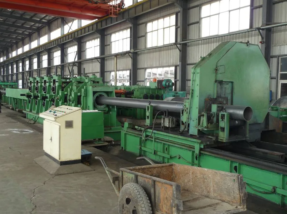
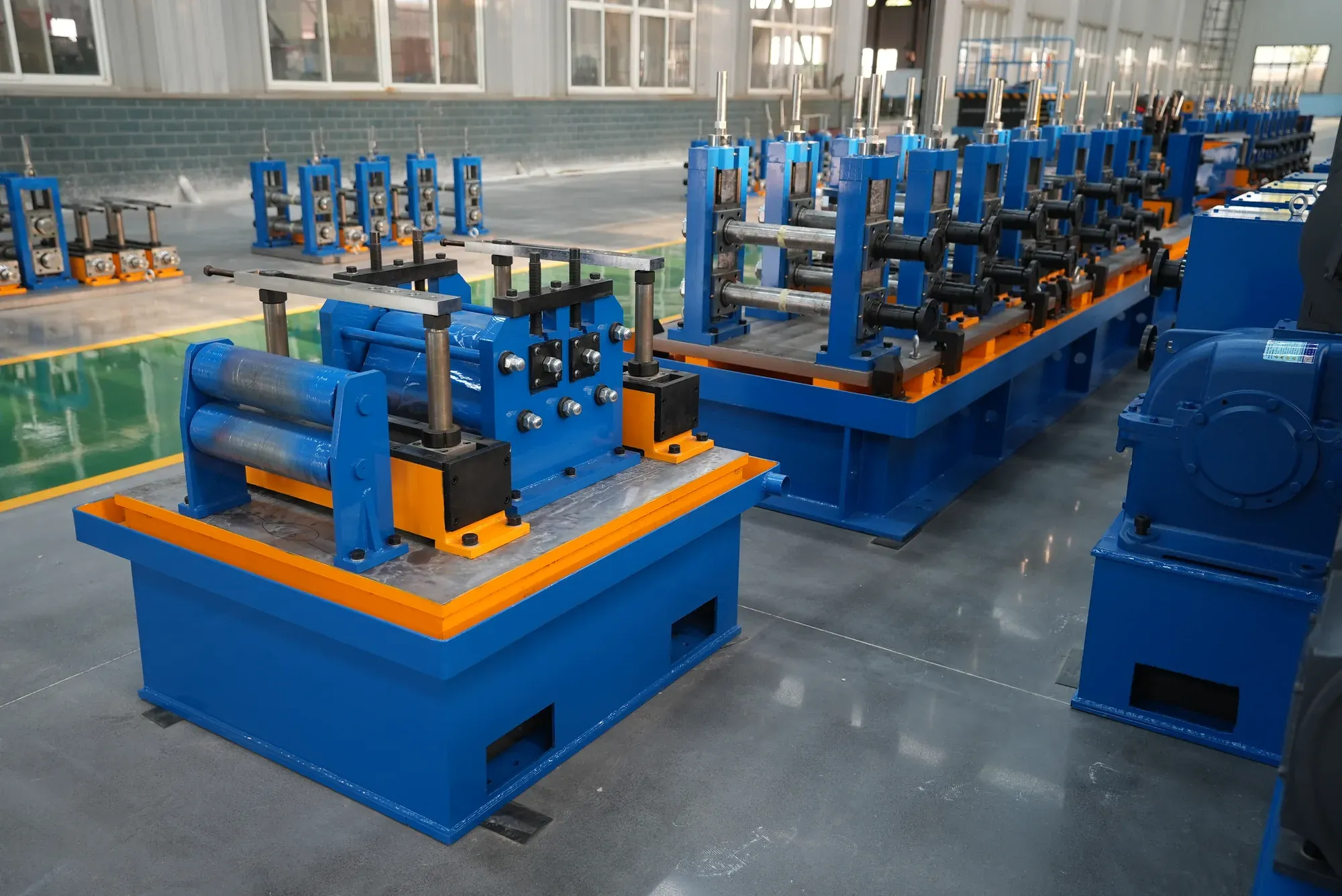
Three inspection stations sit on the finishing line of a spiral mill: X-ray at 225 kVA, a 1200-tonne hydrostatic tester, and off-line ultrasonic. Filmed at the run-out end of lines that carry the inspection chain.
Each has a published, quantified capability rather than a claim.
Why the Inspection Chain Decides the Order
Almost every large-diameter buyer asks the same question: can the spiral weld actually pass X-ray, hydrostatic and ultrasonic in one go? For an end user in energy or line-pipe manufacturing that is not a quality question — it is the order threshold, and a missed defect leaving the works becomes a claim.
So our answer is quantified, not just reassuring. Each of the three stations has a published capability figure, a coverage definition, and a standard it is built against; those are set out below and repeated in the comparison table. Wall thickness, line speed and shift output are confirmed against your pipe size, material grade and cut length at quotation.
Send us those three and we will state the figures.
One boundary also matters, because it decides who is responsible for what after handover. We supply the stations, their quantified capability and the standards reference; daily calibration, reference-block verification and pass/fail adjudication sit with the operator, not with the equipment maker.
Calibration drift or a missing check is how a fully specified line still ships a defective pipe.
X-Ray Inspection: 225 kVA, 0.8–1.2% Sensitivity, 40 mm Fe Penetration
- The X-ray station images the spiral weld to detect internal defects. Published capability:
- Tube rating 225 kV / 8 mA (225 kVA class)
- Maximum penetration 40 mm Fe
- Static sensitivity 0.8–1.2%
- Inspection speed 0.5–10 m/min
- Applicable to Φ219–1620 mm, pipe length ≤ 12 m
- Imaging by digital flat panel. Standards referenced at this station: GB/T 26830-2011, ISO 10893-7 single-wall class B, GB/T 9711-2017 and API SPEC 5L (46th edition); radiation protection to GBZ-117-2015 and GBZ/T 250-2014.
Consumables are worth knowing before purchase: the X-ray tube and its cooler are wear items (XL-225HP/11, XL-2), water-cooled at a flow above 4 L/min with inlet water not exceeding 35 °C.
What moves the result is tube voltage and current, inspection speed, and block calibration — which is why the sensitivity figure is quoted as a static value against a test block rather than as a general claim.
1200-Tonne Hydrostatic Test with Computer-Monitored Printed Record
- The hydrostatic tester proves pressure integrity of the pipe body and the weld. Published capability:
- 1200-tonne frame, Φ800 mm main cylinder, 31.5 MPa high-pressure pump
- Four tension beams, 16Mn 600 × 80, pin holes Φ150 42CrMo, safety factor 4
- Applicable to Φ219–1620 mm, 8–12 m pipe
- PLC plus computer monitoring, with a printed record of each test. The printed record is the part that matters commercially: it is what an end user’s quality department or an EPC’s inspector receives, and it is why hold time and pressure are logged rather than asserted.
| Station | Quantified capability | Coverage | Standard basis |
|---|---|---|---|
| X-ray | 225 kV / 8 mA · 40 mm Fe penetration · static sensitivity 0.8–1.2% · 0.5–10 m/min | Spiral weld, Φ219–1620 mm, ≤ 12 m | GB/T 26830-2011 · ISO 10893-7 single-wall B · GB/T 9711-2017 · API SPEC 5L (46th) |
| Hydrostatic | 1200 t frame · Φ800 main cylinder · 31.5 MPa pump · safety factor 4 | Pipe body and weld, Φ219–1620 mm, 8–12 m | Pressure and hold logged; computer-monitored printed record |
| Off-line ultrasonic | 0.5–15 MHz · 32 channels pipe body / 8 channels weld · false-call ≤ 2% · zero missed calls on sample pipe | Weld 100% · HAZ 25 mm each side · pipe body ≥ 35% | GB/T 9711-2017 · API SPEC 5L (46th) |
The finishing sequence these stations sit in runs: weld repair → pipe-end alignment → X-ray → 1200-tonne hydrostatic → off-line ultrasonic → end facing and bevelling. Each station passes, reworks or rejects; repaired welds are re-inspected. Pipe-end dead zone is ≤ 300 mm.
Off-line ultrasonic completes the chain and is the station with the widest coverage definition: weld 100%, heat-affected zone 25 mm each side, and pipe-body base material at 35% or better, using water-film coupling and multi-channel probes at 0.5–15 MHz — 32 channels on the pipe body and 8 on the weld.
Published performance is a false-call rate of 2% or less with zero missed calls on the sample pipe. Acceptance is against GB/T 9711-2017 and API SPEC 5L (46th edition).
Operationally, three things decide whether the chain holds: probe calibration against reference blocks, hold time and pressure at the hydrostatic station, and re-inspection after any weld repair. Repaired welds go back through, and the pipe-end dead zone of 300 mm or less has to be handled by the operator’s own procedure.
Operators need trained, qualified NDT personnel for this section of the line — the equipment does not adjudicate.
A related but separate chain applies to API line pipe on the high-frequency side: an API mill adds intermediate-frequency annealing, straightening, end facing, hydrostatic testing, ultrasonic and eddy-current inspection to a standard welded-tube line, covering OD 114–508 mm at 6–24 mm wall by class.
Weld tracking on the line uses laser image capture, which is what keeps the X-ray station looking at the seam rather than near it.
From the Workshop
Send Your Enquiry
Tell us the pipe outside-diameter range, the wall thickness and the output you need. An engineer reads every enquiry — it does not land in a general sales inbox.