
 Scan on WeChat
Process Films
Process videos show a tube mill doing what its specification claims: strip uncoiled and levelled, formed by rolls, closed by high-frequency induction welding, sized, straightened and cut to length by flying saw — with the line never stopping between coils.
Coil entry to finished pipe, filmed on our own floor.
How a Tube Mill Line Runs, Stage by Stage
An automatic shear-welder cuts off the irregular head and tail of each coil and joins one strip to the next; a spiral accumulator stores strip between that unit and the mill, feeding the mill while the next coil is being prepared. A high-frequency welded tube mill is a continuous line: flat strip enters at one end and cut lengths of welded pipe leave at the other, without the mill stopping when one coil runs out.
Without the accumulator the mill stops at every coil change; with it, the joint passes through as part of a continuous run.
Ahead of those, two preparation stages set up everything downstream. The coil is loaded by coil car onto an expanding-mandrel uncoiler and tensioned pneumatically — poor centring or tension shows up much later as a wandering strip. Then a five-roller leveler flattens it, because residual curvature in the strip becomes a forming ridge or a weld offset further down the line.
Continuity is the part worth understanding first, because it is what separates a production line from a machine. Two units make it possible.
HF Induction Welding on the Line
High-frequency welding closes the seam without filler: the HF current concentrates at the edges through skin and proximity effect, heats them to welding temperature, and squeeze rolls press them together.
Welder power itself is matched to diameter in steps across the range 150–1500 kW. (HG50 / HG76 / HG89 / HG114 / HG165 / HG219 / HG273 / HG325 / HG426 / HG508) is quoted per project; the two endpoints are HG32 = 150 kW and HG630 = 1500 kW.
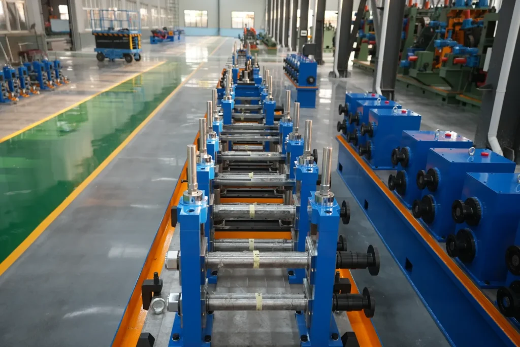
Forming precedes it and decides whether the seam can be welded well at all: forming rolls bring the flat strip progressively to the required round or square section, and this stage sets both tube shape and seam alignment.
What the video shows that a diagram cannot is how tightly three variables have to stay matched — welder power, line speed and squeeze. Mismatch does not produce a slightly worse weld; it produces a specific and recognisable defect. Too little energy gives lack of fusion or a cold weld; too much gives burn-through. Either one fails a pressure or NDT check downstream.
Sizing, Straightening and Flying-Saw Cut-Off
After the weld cools, sizing rolls bring the tube to final outside diameter and straighten it; a flying saw then cuts to length at full line speed without stopping the mill.
Underneath all of it sits the control layer — PLC industrial computer with variable-frequency drive — which is what keeps line speed and cut length repeatable run after run.
Two further things are worth watching for, because they are what a buyer is really assessing.
The first is size change. On direct-square-forming lines, size is changed by combined dies rather than by changing rolls, and roll consumption falls by more than 90%; servo adjustment and quick die change carry the rest. For a plant running several sizes this is the difference between a shift lost to changeover and an hour lost to it — and it is far more convincing watched than tabulated. One exception is worth stating: making 100 × 100 mm tube needs the upper roll on the final open stand changed.
The second is yield. Across the lines, material yield runs at 93% or better; roll wear and changeover speed are the two things that move it.
Video is also the fastest way to learn what each stage fails like, which is worth knowing before a line is bought rather than after. Uncoiler centring or tension that is off shows as a wandering or slack coil, and the strip arrives at forming already out of position. Levelling that is under-adjusted leaves residual curvature, which reappears as a forming ridge or a weld offset.
A poor strip-weld joint cracks or misaligns, which either stops the line or produces a scrap length at the joint. Accumulator storage or tension that is misjudged starves the mill or lets it judder, and the weld quality moves with it.
Further down, forming pass or roll-gap error gives an uneven opening and out-of-round or out-of-square section, which in turn puts the seam off-centre; and sizing or straightening set wrong gives OD out of tolerance or a bowed tube.
The eight stages, in order: 1. Uncoiling — coil car and expanding-mandrel uncoiler, pneumatic tensioning 2. Head straightening and levelling — five-roller leveler 3. Shear and strip welding — automatic shear-welder joins coil to coil 4. Spiral accumulator — strip buffer for non-stop running 5. Roll forming — progressive forming to round or square section 6.
HF induction welding — skin/proximity heating, squeeze rolls close the seam 7. Sizing and straightening — final dimension and straightness after cooling 8. Flying-saw cut-off — cut to length at line speed
Ask an Engineer — Reply Within a Single Contact →
Sizing and straightening decide final dimensional accuracy and straightness — misadjusted sizing rolls give out-of-tolerance OD or a bowed tube. Cut-off is the one stage the material does not forgive twice: the saw travels with the pipe while cutting, so length error and end burr both trace back to saw tracking and clamping rather than to anything upstream.
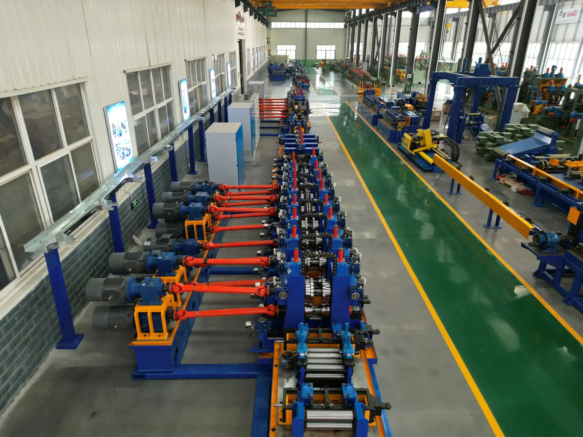
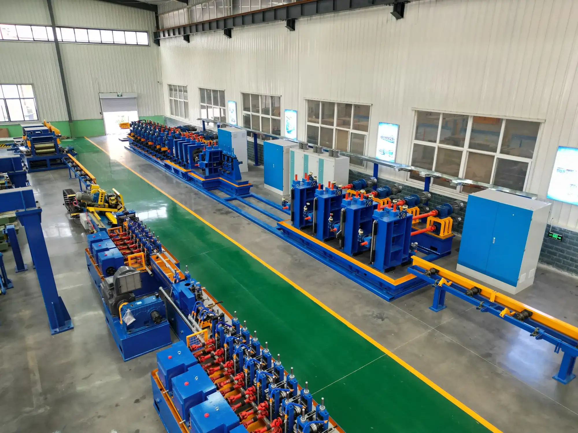
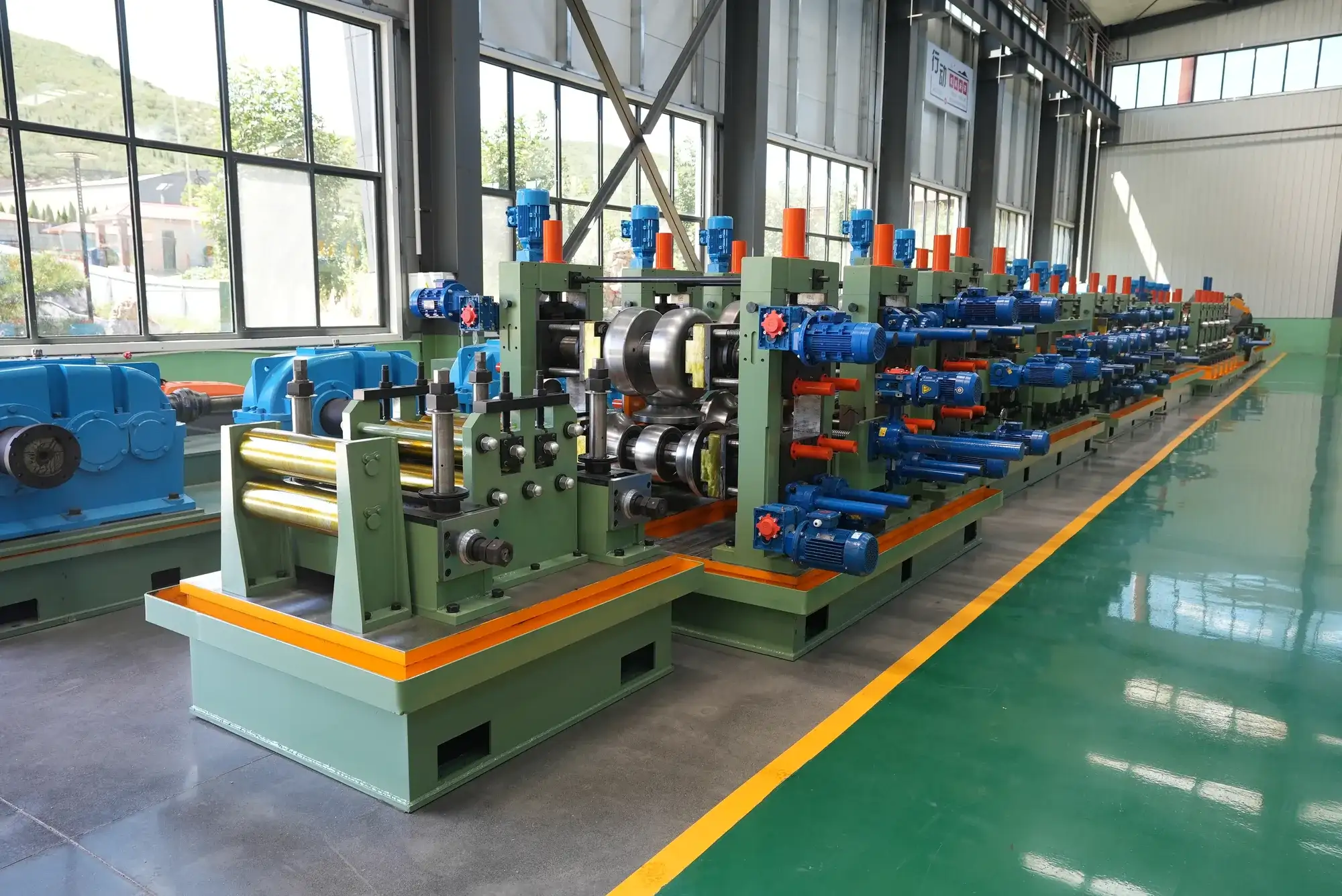
From the Workshop
Send Your Enquiry
Tell us the pipe outside-diameter range, the wall thickness and the output you need. An engineer reads every enquiry — it does not land in a general sales inbox.