 Scan on WeChat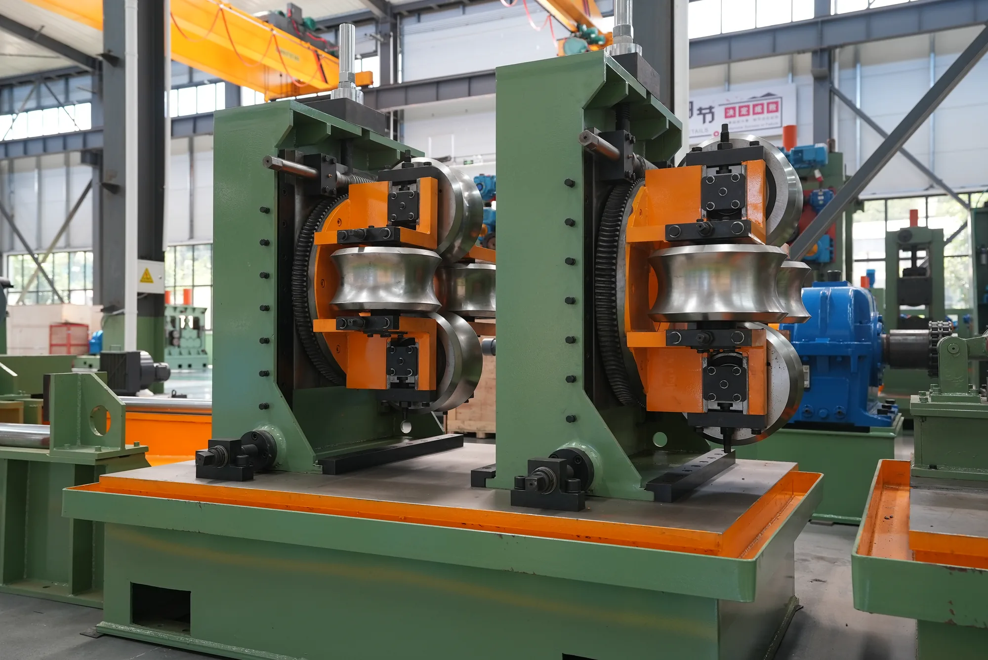
Oil & Gas Line Pipe Mill
Home › Pipe Production Applications › Oil & Gas Line Pipe Mill
Producing oil and gas line pipe is not a matter of making pipe and testing it afterwards.
In This Line
Quick Contact
Hebei TengtianYuanle@tentubemill.com
+86-311-83025332
WhatsApp +852 5425 3155
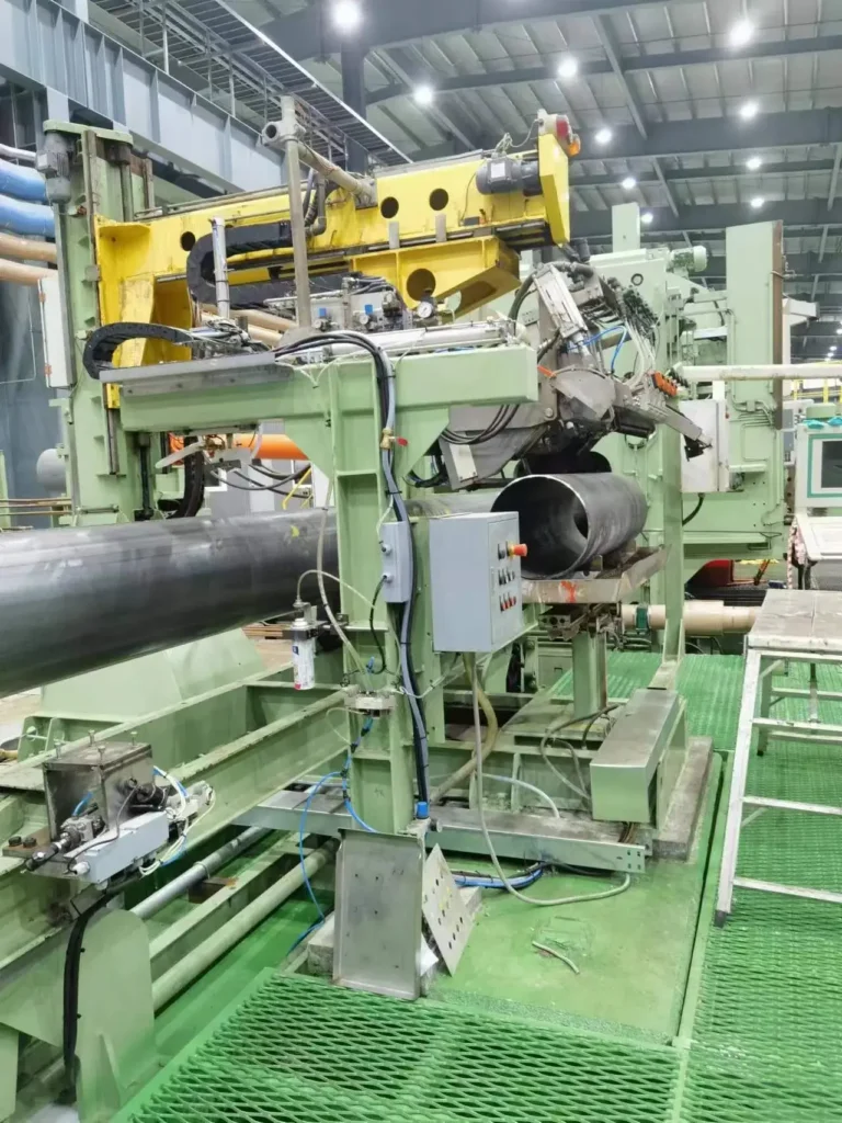
The inspection chain is built into the mill: post-weld annealing, hydrostatic testing, ultrasonic and eddy-current inspection are line stations, not a laboratory.
What Is Oil & Gas Line Pipe Production
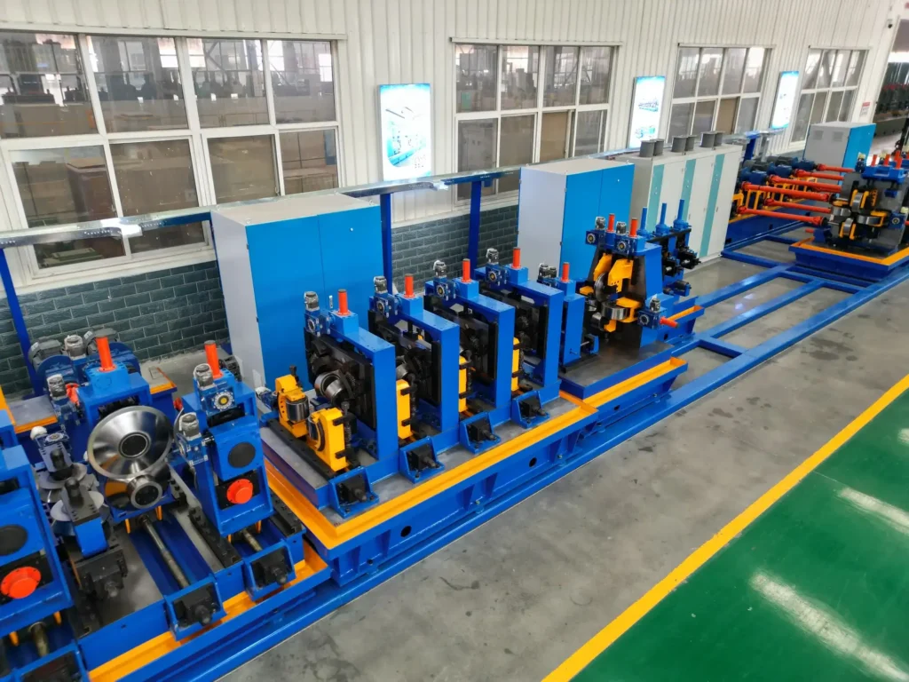
An oil and gas line pipe mill is a welded pipe line with a compliance chain attached: the same forming and welding as a standard mill, plus medium-frequency annealing, straightening, end facing, hydrostatic testing, ultrasonic and eddy-current inspection.
That is the compliance grading, and it is what separates two quotations that look similar on diameter and output. Wall thickness, line speed and shift output are confirmed against your pipe size, material grade and cut length at quotation. Send us those three and we will state the figures.
Why the inspection stations are on the line rather than at the end: hydrostatic, ultrasonic and eddy-current run in line, testing seam and pipe body and adjudicating pass or reject against the standard as the pipe is produced — which is also what makes the result traceable pipe by pipe.
For end users in energy and infrastructure, this is not a quality preference — it is the order threshold. Weld performance and compliance inspection are what the order is written against; a missed defect leaving the works becomes a claim.
The six post-weld stations are worth understanding individually, because a quotation that omits any one of them is quoting a different machine.
Annealing comes first and is metallurgical rather than dimensional: medium-frequency heating of the weld zone followed by natural cooling, which improves the structure and toughness of the seam and its heat-affected zone. Annealing temperature and heating power are the variables, and they are what decide whether weld mechanical properties meet the specification at all.
Straightening and end facing follow, and they are what make the pipe usable on a pipeline rather than merely sound. A pipe that is metallurgically perfect but bowed, or square-cut but not bevelled, cannot be laid and welded in the field.
Then the three inspection stations, and their order is not arbitrary. Hydrostatic testing proves pressure integrity of body and seam under internal pressure. Ultrasonic inspection finds internal discontinuities the pressure test would not reveal. Eddy-current inspection covers surface and near-surface defects that ultrasonic is poorly placed to see.
What keeps that chain honest is not the equipment but the discipline around it: inspection parameters, calibration and adjudication criteria.
Why annealing is in that list rather than optional: high-frequency welding leaves the weld zone harder and less tough than the parent material. Medium-frequency annealing reheats that zone and lets it cool naturally, improving the metallurgical structure and toughness of the weld and its heat-affected zone. Without it, weld-zone mechanical properties are what fail the specification.
Target Pipe Sizes and Wall Thickness for This Application
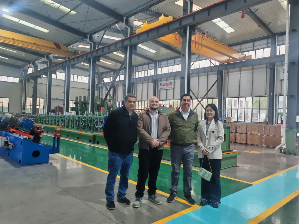
HFW route with API post-weld chain — API 219 / 406 / 426 / 508 classes, outside diameter 114–508 mm, wall 6–24 mm by class.
Spiral submerged-arc route — two classes, Φ219–820 mm × 3–12 mm and Φ219–1620 mm × 5–16 mm, pipe 8–12 m, single-pipe weight to 7.5 t. Diameter is changed by forming angle (39°–80°) rather than by roll change.
On the spiral side the line-pipe case sits at the large end: Φ820–1620 mm produced to GB/T 9711 or API 5L, each pipe X-rayed, hydrostatically tested and ultrasonically inspected before release.
Wall thickness is where the two routes diverge most sharply, and it is worth reading against the application rather than in isolation. The HFW-API route carries 6–24 mm by class — a heavier wall band than the standard HFW range, which is part of what the API configuration buys. The spiral route carries 5–16 mm, across a diameter band three times wider.
So a requirement for heavy wall at moderate diameter points one way, and thin-to-medium wall at large diameter points the other.
Pipe length and handling matter more on line pipe than on general tube, because the pipe is laid rather than cut down. On the spiral route pipe is produced at 8–12 m with single-pipe weight to 7.5 t on the Φ1620 class — figures that decide site handling equipment before they decide anything about the mill.
Line pipe for oil and gas spans a diameter range no single welding technology covers, so this application is served by two mill routes rather than one.
| Route and class | Outside diameter | Wall thickness | Also covered |
|---|---|---|---|
| HFW, API line-pipe classes 219 / 406 / 426 / 508 | Φ114–508 mm | 6–24 mm by class | Post-weld annealing, hydrostatic, ultrasonic and eddy-current as line stations |
| Spiral submerged-arc, class 1 | Φ219–820 mm | 3–12 mm | Pipe length 8–12 m |
| Spiral submerged-arc, class 2 | Φ219–1620 mm | 5–16 mm | Single-pipe weight to 7.5 t; diameter set by forming angle 39°–80° |
Recommended Mill Model and Welder Power Band
Above Φ508 mm the HFW-API route runs out and the spiral route is what makes the pipe. Which route fits is decided by the largest diameter the plant intends to sell, then by wall thickness, then by the standard the finished pipe must satisfy.
Batch size deserves its own line here because the two routes behave differently under it. The spiral route is discontinuous — pipe by pipe, at 0.5–3 m/min welding speed — which suits large diameter in medium batches. The high-frequency route is continuous, running across coil changes without stopping, which suits volume in a narrower diameter band.
For a line-pipe project measured in kilometres of a single specification, that difference usually decides more than diameter does.
The standard the finished pipe must satisfy is the third input, and on this application it is often the first one the buyer states. The spiral Φ1620 class is built against GB/T 9711 and API SPEC 5L; the Φ820 class against GB/T 9711 and GB/T 5037; the HFW-API route against API 5L.
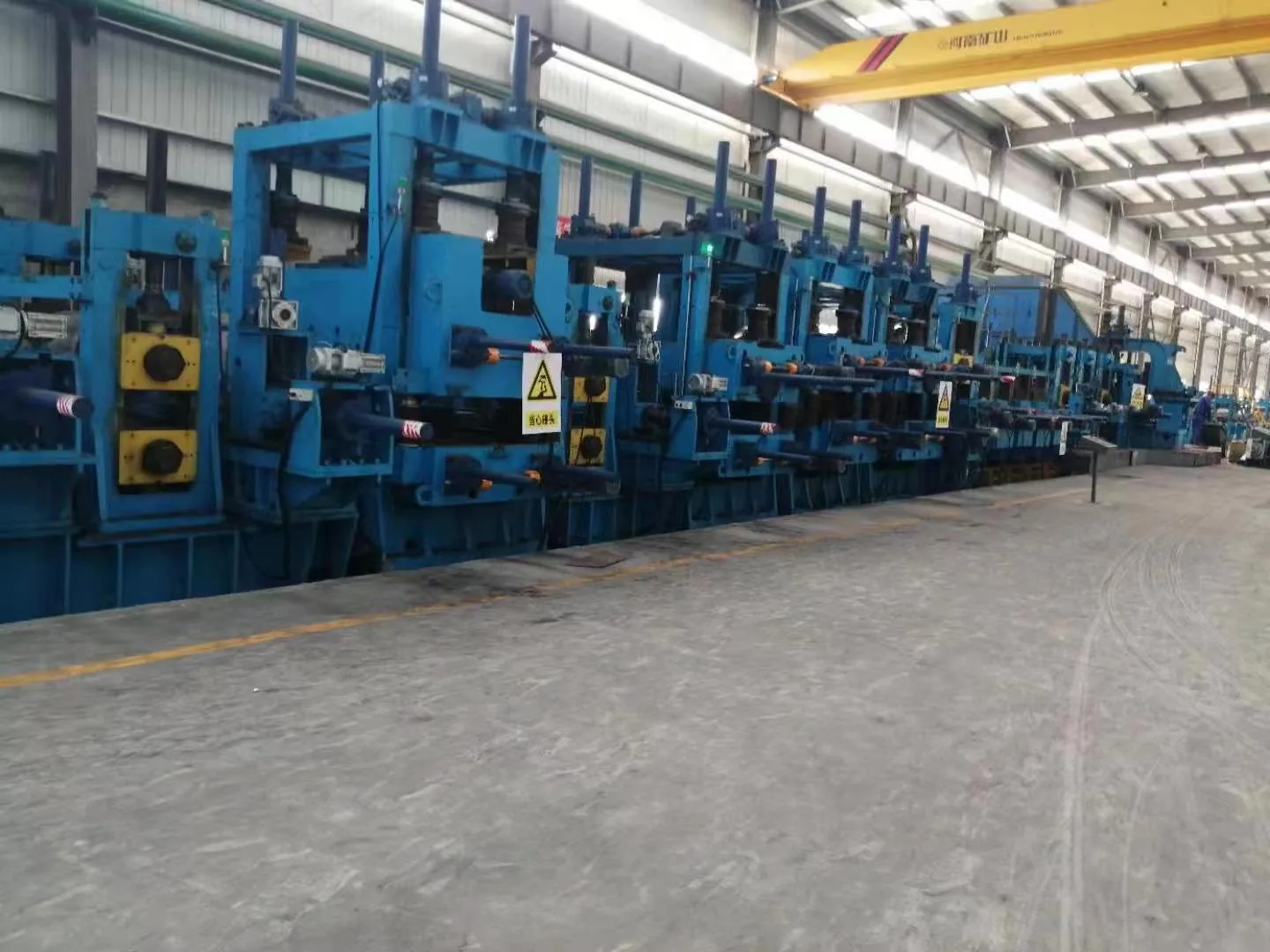
Welder power is matched to diameter in steps across 150–1500 kW. HG630 = 1500 kW. Intermediate model ratings are quoted per project.
Below it both can, and the decision moves to wall, batch size and which inspection chain the buyer’s specification names.
Applicable Standards and Inspection Requirements
| HFW-API route | Spiral (SSAW) route | |
|---|---|---|
| Diameter × wall | Φ114–508 mm × 6–24 mm by class | Φ219–1620 mm × 5–16 mm |
| Model classes | API 219 / 406 / 426 / 508 | Φ820 class and Φ1620 class |
| Post-weld treatment | Medium-frequency annealing + straightening + end facing | Weld repair + end facing / bevelling |
| Inspection chain | Hydrostatic + UT + ECT, in line | X-ray + hydrostatic + off-line ultrasonic |
| X-ray capability | — (not on this route) | 225 kV / 8 mA, 40 mm Fe, sensitivity 0.8–1.2% |
| Hydrostatic | In-line hydrostatic test unit | 1200 t frame, Φ800 cylinder, 31.5 MPa, printed record |
| Ultrasonic | In-line UT | Off-line, 0.5–15 MHz, weld 100%, HAZ 25 mm each side, body ≥35% |
| Eddy current | ECT in line | — (not on this route) |
| Operative standard | API 5L | GB/T 9711; API SPEC 5L (Φ1620 class) |
X-ray runs at 225 kV / 8 mA with 40 mm Fe penetration and static sensitivity 0.8–1.2%, at 0.5–10 m/min, against GB/T 26830-2011, ISO 10893-7 single-wall class B, GB/T 9711-2017 and API SPEC 5L (46th edition).
NDT consumables — couplant and calibration blocks — are replenished by inspection volume; Tengtian can advise specification and sourcing.
Hydrostatic testing uses a 1200-tonne frame with a Φ800 mm main cylinder and a 31.5 MPa pump, four tension beams at safety factor 4, PLC and computer monitoring with a printed record.
Off-line ultrasonic runs 0.5–15 MHz, covering the weld 100%, the heat-affected zone 25 mm each side and pipe body base material at 35% or better, with false calls at or below 2% and zero missed calls on the sample pipe. Weld tracking uses laser image capture.
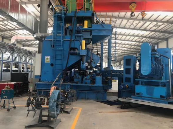
Finishing on the spiral Φ1620 class runs slag removal, weld repair, pipe-end alignment, X-ray, hydrostatic test, off-line ultrasonic, then end facing and bevelling; repaired welds are re-inspected, and the pipe-end dead zone of 300 mm or less is handled by the operator’s own procedure. The Φ820 class runs a shorter chain: weld repair, X-ray, end facing, hydrostatic.
Inspection is only as good as its upkeep, and the boundary is worth stating before acceptance: the equipment supplies the stations, their capability and the standards reference; NDT parameter setting, calibration against reference blocks and pass/fail adjudication sit with the plant’s qualified personnel. Drifting calibration is how a fully specified line still releases a non-compliant pipe.
Worked Output Example
The example below is for the spiral route; on the HFW-API route, output is confirmed at quotation.
Spiral route, Φ1620 class — output is set at approximately 120 tonnes per 8-hour shift; the Φ820 class at approximately 62 tonnes per 8-hour shift.
Manufacturing lead time on the spiral route is 120 days(Φ820)/ 150 days(Φ1620).
Plant requirements for the spiral route: workshop 36 × 24 m with a 32 t crane at 6.5 m hook height for the Φ1620 class, or 32 × 18 m with a 20 t crane at 7 m for the Φ820 class; supply 220 / 380 V 50 Hz and compressed air at 0.6 MPa. Feed direction can be set left or right to suit an existing building.
The third case is a configuration problem before it is a machine problem, and it is worth checking against the scope levels before concluding the mill has to be replaced.
Commercially, terms are the same as across the range: tiered configuration mapped to a written scope of supply, staged payment, an adjustable deposit ratio, third-party escrow and several workable Incoterms. Installation, commissioning and operator training sit inside the after-sales scope, with engineers dispatched to site and support continuing online after handover.
Acceptance on the spiral route is defined as continuous production of two different pipe sizes.
Carbon steel pipe mill for fluid transport
Oil and gas transmission pipe mill
From the Workshop
 Water Supply, Drainage & Urban Gas Pipe Production Lines
 Structural & Scaffolding Tube Production
 Furniture & Fence Tube Production
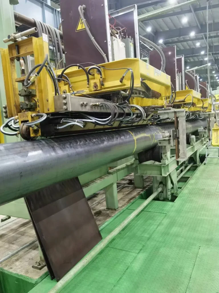 The API Pipe Mill Inspection Chain
Send Your Enquiry
Tell us the pipe outside-diameter range, the wall thickness and the output you need. An engineer reads every enquiry — it does not land in a general sales inbox.