
 Scan on WeChat
Home › High-Frequency Welded Pipe Mill › How the Weld Seam Heats: Skin and Proximity Effect
In This Line
Quick Contact
Hebei TengtianYuanle@tentubemill.com
+86-311-83025332
WhatsApp +852 5425 3155
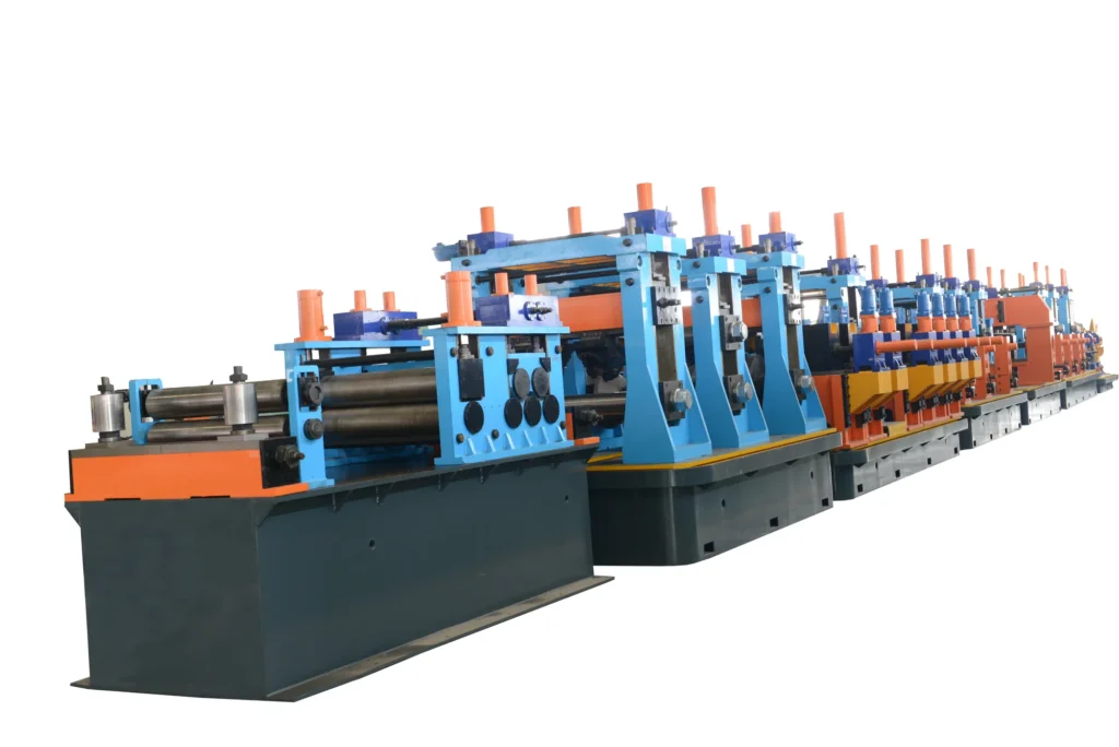
High-frequency induction welding concentrates current at the open edges of the tube blank through skin and proximity effects, heating them to welding temperature; squeeze rolls then press the two edges together into a continuous seam. Welder power is matched to pipe diameter across a 150 to 1500 kW range.
How the Seam Is Heated and Forged
- Skin and proximity effects concentrate high-frequency current at the seam edges of the open blank.
- Squeeze rolls forge the heated edges together into a continuous seam.
- The three governing parameters are power, frequency and weld speed.
- Welder power is matched to pipe diameter, from 150 kW on HG32 up to 1500 kW on HG630.
- The induction coil and impeder are the components that do the concentrating, and they are wear parts.
How HF Induction Welding Works
The two heated edges are brought together under pressure from the squeeze rolls and forged into a continuous seam; the process is classed as solid-state or fusion pressure welding. High-frequency induction welding is a pressure welding process, not a filler process. After the forming rolls have bent the flat strip progressively into a round or square open blank, the two edges of that blank approach each other in a V.
The joint itself is then made mechanically.
After welding the tube is cooled, then sized by the sizing rolls to final outside diameter and given a first straightening pass, which is what fixes final dimensional accuracy and straightness.
How does high frequency welding work
The reason the process is fast is the same reason it is fussy. Because the heat is concentrated in a very narrow zone rather than spread through the section, the line can weld continuously at production speed — but the heat input has to stay matched to the edge geometry as it moves.
Three parameters govern that match: current frequency, power, and weld speed. Together they determine whether seam heating stays concentrated, how much energy is consumed, and whether the edges actually fuse.
The failure modes are correspondingly specific. When high-frequency parameters are mismatched the results are lack of fusion, cold welds and burn-through; when power or frequency is unstable, the pipe also fails pressure testing and non-destructive inspection.
High-frequency current is induced in the blank, and because of the skin effect and the proximity effect it does not spread over the whole section — it concentrates at the open edges, precisely where the seam will be, and heats that narrow zone rapidly to welding temperature.
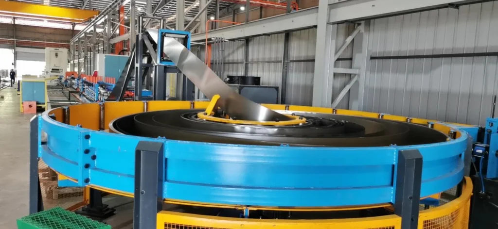
How HF Induction Welding Works — Method and Measured Values
Welder power is matched to pipe diameter across 150 to 1500 kW; the HG32 band is set at 150 kW and the HG630 band at 1500 kW.
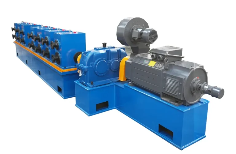
The welder supplies the welding energy and therefore determines seam fusion quality and welding speed. Tengtian’s line proposals specify a solid-state high-frequency welder; confirm the welder type and rating fitted to the line you are quoted.
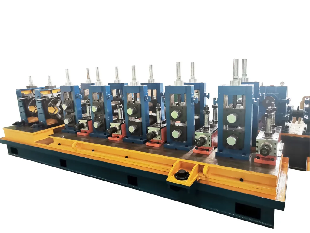
High frequency induction welding process
The induction coil and the impeder concentrate high-frequency current at the seam through skin and proximity effects, and they directly affect welding thermal efficiency and weld quality; when they wear out or fail, welding energy disperses, weld quality fluctuates and energy consumption rises. They are wear parts with continuing supply, replaced periodically.
The other half of the joint is mechanical. Squeeze amount and seam alignment are a quality-influencing factor in their own right, with weld-seam misalignment, edge mismatch and burrs as the symptoms, and forming alignment plus squeeze-roll control as the control points.
Post-weld cooling is a process and equipment factor: it stabilises seam structure, and the consequences of getting it wrong are poor seam structure and distortion. The control points are cooling stability and matching cooling to weld speed.
The induction coil and the impeder are the two components that do the physical work, and each has its own failure modes.
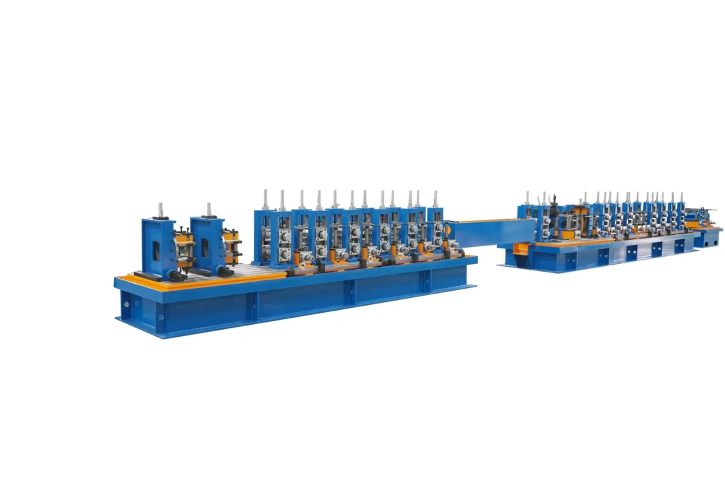
Standards Behind Our Welding Practice
GB/T 9711 is on both spiral bands with GB/T 5037 on the 820 band and API 5L on the 1620 band; API 5L applies to the API line pipe family; GOST R 58966-2020 for the H-beam line; and the enterprise standard Q/GYLTT01-2023, covering HGF150 high-frequency welded pipe equipment, was issued on 31 August 2023 and took effect on 15 September 2023.
These are product and equipment standards, not welding-process standards.
Step-by-Step Procedure
Squeeze rolls press the heated edges together to form the continuous seam. Forming rolls bend the strip progressively into the open blank. High-frequency current, concentrated at the seam by skin and proximity effects, heats the edges to welding temperature. The tube is cooled after welding.
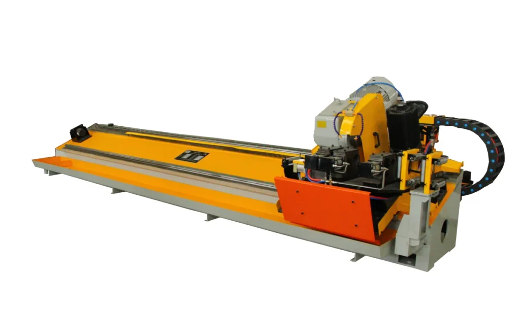
Sizing rolls bring it to final outside diameter and a first straightening pass sets straightness. A flying saw cuts to length while pipe continues to be delivered at speed.
On the operating side, the step is to set welder power and weld speed, start the continuous forming–welding–sizing run, and monitor the process.
Worked Example — Welder Power for Your Diameter
For a mill targeting Φ32 mm pipe, the band is HG32 and the welder power for that band is 150 kW. At the other end of the range, for a mill targeting Φ630 mm, the band is HG630 and the power is 1500 kW.
Power alone does not give you energy cost; that also needs weld speed, duty cycle and your electricity tariff. What can be said is the direction: when the induction coil or impeder deteriorates, energy consumption rises, though the increase is not quantified.
What “high frequency” buys, and what it costs in discipline
The same narrowness is why the three parameters have to stay matched: frequency, power and weld speed together decide whether heating stays concentrated, how much energy is consumed, and whether the edges fuse at all.
Mechanically the same discipline applies at the squeeze rolls. Squeeze amount and seam alignment are a factor in their own right, and the defects linked to them — misalignment, edge mismatch and burrs — are the ones a buyer will see on the finished pipe rather than on a chart.
The control points are forming alignment and squeeze-roll control, which is another way of saying that the weld inherits whatever the forming section handed it.
Control stability closes the loop. PLC and variable-frequency drive stability is what keeps line speed and cut length repeatable, with speed fluctuation and length error as the failure modes; the control system coordinates the cycle and speed of forming, welding, sizing and cutting.
These factors are described by variable and associated defect, not by tolerance band. That is enough to compare suppliers on process understanding; an acceptance specification also needs tolerance values agreed for the order.
What to ask the factory for
Four questions turn a general enquiry into a specification. Ask for the welder power of the specific band required, not just the two endpoints. Ask for the operating frequency. Ask for the welder type and rating supplied with the line.
And ask for weld speed at the target wall thickness — that is the number that turns power into output.
Why the forming stage decides the weld
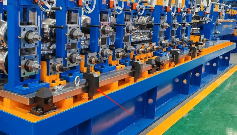
Weld quality starts before the weld box. The seam is only as good as the edges presented to it, and those edges are set upstream. Forming rolls rotate continuously against the strip and bend it pass by pass into the open blank; the parameters for that are pass count, roll gap and roll form, and what they determine is shape accuracy and seam alignment.
The cause-and-effect chain makes the dependency explicit: incorrect adjustment of forming passes or roll gap produces an uneven open seam and shape deviation, which then causes weld-seam misalignment and out-of-tolerance roundness or squareness. Before that, the five-roll pre-leveller has to have taken residual curvature out of the strip, or the same defects appear from a different cause.
That is why forming roll material counts as a quality factor alongside the welding parameters. Roll material and heat treatment govern shape stability, with shape deviation, early roll wear and an uneven corner line as the failure modes.
Where the process sits in the line
The welding stage is one of eight process stages.
Coil is uncoiled; the head is flattened and the strip levelled; head and tail are sheared and butt welded so a coil change does not stop the line; a spiral accumulator stores strip through that join; rolls form the blank; high-frequency welding closes the seam; the tube is cooled, sized and straightened; and a flying saw cuts it to length at speed.
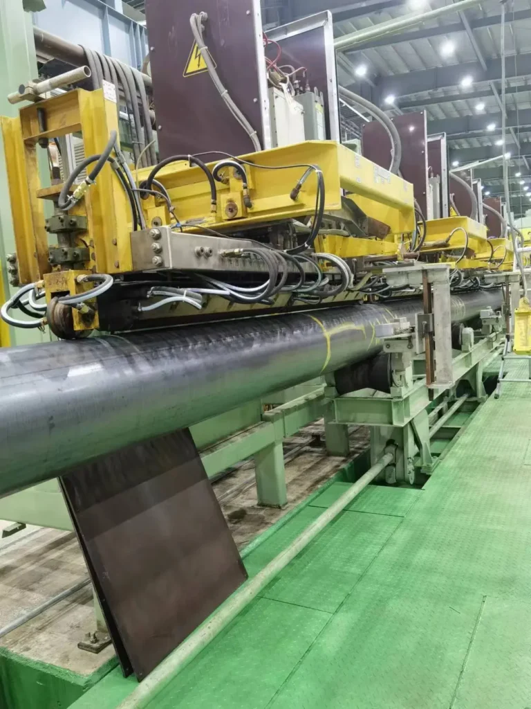
Two of those neighbours interact with welding directly. Post-weld cooling stabilises seam structure and has to be matched to weld speed. Final inspection is the catch for anything the weld got wrong, with ultrasonic and eddy-current testing on API line-pipe configurations.
How this compares with the alternatives
Against spiral submerged-arc welding, high-frequency welding is faster in welding speed, straight-seam rather than spiral, and suited to structural and conventional fluid pipe; the spiral route changes diameter by changing the forming angle instead of changing rolls,
which gives one machine a wide diameter span and large heavy-wall capability, but at a welding speed of 0.5 to 3 metres per minute.
Against seamless rolling and UOE or JCOE forming, the high-frequency route is lower in investment and running cost and more continuous, suited to high-volume small and medium diameter production.
The wear parts question
Because the coil and impeder are what concentrate the current, their condition is a running cost and a quality variable at the same time. As they deteriorate, welding energy disperses, weld quality fluctuates and energy consumption rises. They are wear parts, replaced periodically and supplied on a continuing basis.
The trade for this process is narrow heat against tight control. Because current concentrates at the edges instead of spreading through the section, the heated zone is small and the line can run continuously at production speed, which is the reason the family suits high-volume small and medium diameter work.
Resource Downloads
From the Workshop
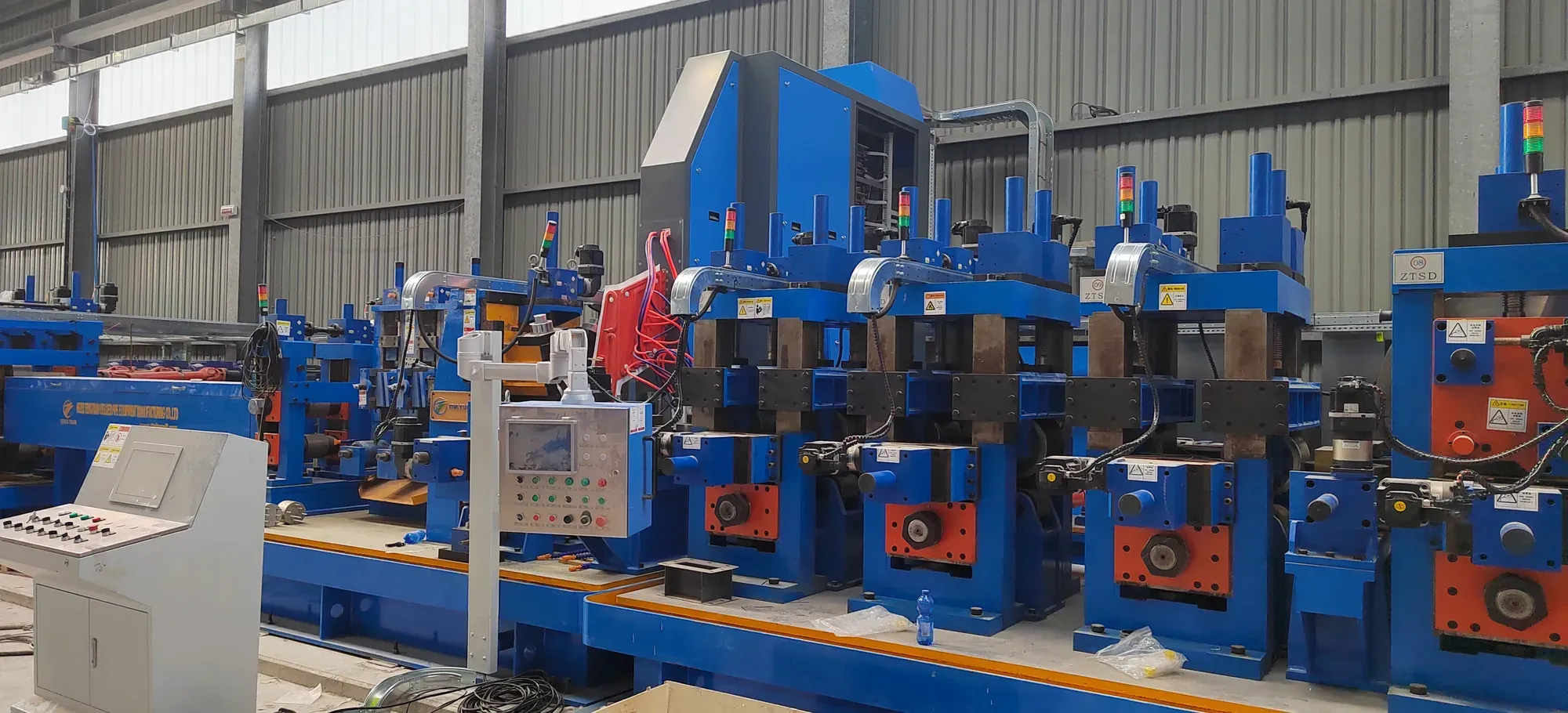


 Sizing the Welder to the Pipe Diameter
 The API Pipe Mill Inspection Chain
 Pipe Coating Line Configuration
 H Beam Welding Line
Send Your Enquiry
Tell us the pipe outside-diameter range, the wall thickness and the output you need. An engineer reads every enquiry — it does not land in a general sales inbox.