 Scan on WeChat
Home › SSAW Spiral Welded Pipe Mill › X-Ray, Hydrostatic and Ultrasonic, Station by Station
In This Line
Quick Contact
Hebei TengtianYuanle@tentubemill.com
+86-311-83025332
WhatsApp +852 5425 3155
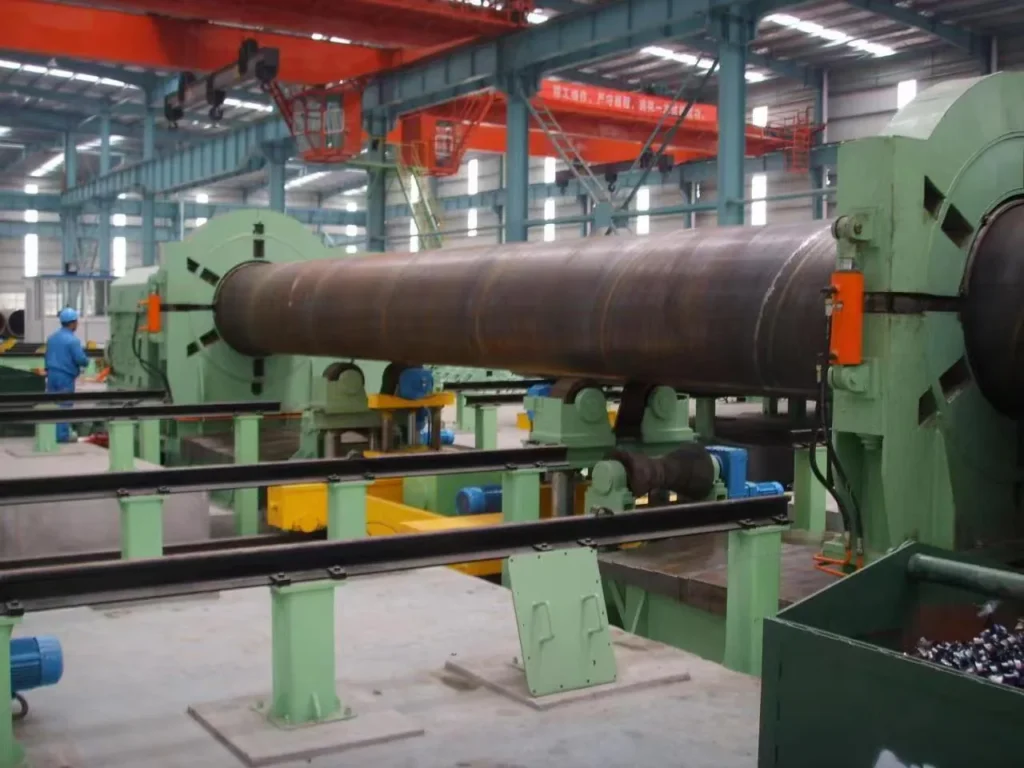
The spiral line can be supplied with a three-stage inspection chain: 225 kVA X-ray, a 1200-tonne hydrostatic tester and offline ultrasonic covering 100 per cent of the weld and not less than 35 per cent of the pipe body. Every stage carries a stated figure.
What Each Inspection Station Is Rated For
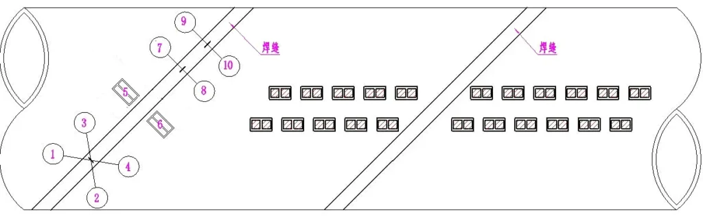
- X-ray: 225 kV / 8 mA, static sensitivity 0.8–1.2%, maximum penetration 40 mm Fe.
- X-ray inspection speed: 0.5–10 m/min, for pipe Φ219–1620 mm up to 12 m.
- Hydrostatic tester: 1200 tonnes, Φ800 main cylinder, 31.5 MPa pump, computer monitoring with printed records.
- Offline ultrasonic: weld 100%, HAZ 25 mm each side, body coverage ≥35%, 0.5–15 MHz.
- Ultrasonic acceptance indices: false call ≤2%, zero missed calls on the sample pipe, end dead zone ≤300 mm.
The Three-Stage Inspection Chain, in Order
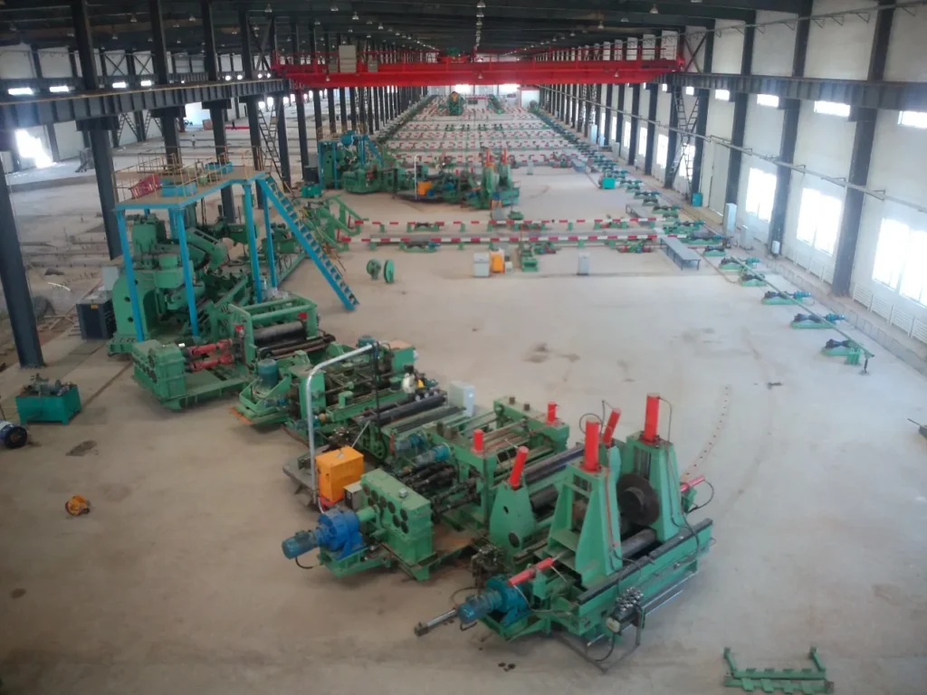
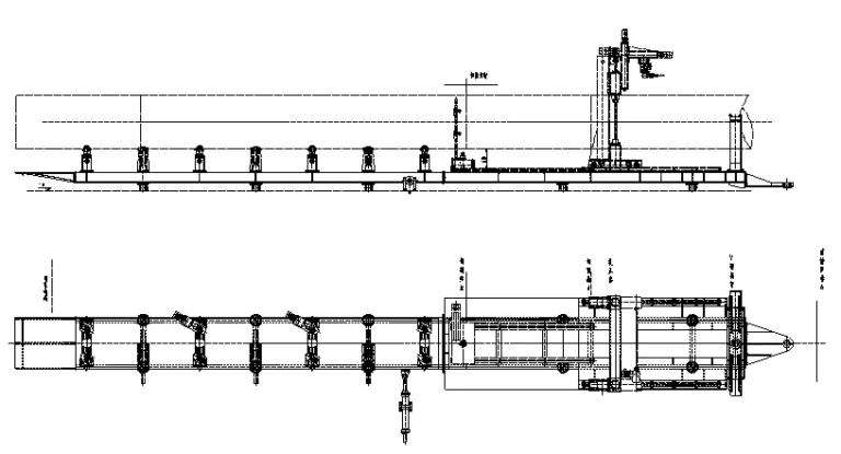
On the Φ1620 grade the finishing sequence runs pipe off-line, slag removal, weld repair, the butting device, X-ray, hydrostatic test, offline ultrasonic, then end facing and chamfering before the pipe is released. The inspection chain on a spiral line is three stations working in sequence, and each line grade gets a defined set of stations.
On the Φ820 grade the sequence is shorter: weld repair, X-ray, end facing, hydrostatic test, finished.
Ultrasonic finds longitudinal and transverse weld defects, delamination in the heat-affected zone, and delamination in the parent body — three defect classes the other two stations do not address.
The consequence of a missing station or a drifting calibration is commercial: defects leave the plant undetected, the pipe cannot be delivered as line pipe, and the outcome is rejection and claims. That is why the whole finishing sequence is where pipe quality is decided, not just a final check.
The question buyers put to us is simple: will a large-diameter, heavy-wall spiral weld pass X-ray, hydrostatic and ultrasonic inspection first time?
The answer is not a reassurance but a set of figures — X-ray sensitivity 0.8 to 1.2 per cent and maximum penetration 40 mm of iron; ultrasonic covering 100 per cent of the weld plus not less than 35 per cent of the body with false calls not more than 2 per cent and zero missed calls on the sample pipe;
and hydrostatic testing on the 1200-tonne machine held to standard with printed records.
The reason the question is legitimate is too: on large-diameter pipe, weld compliance is the delivery gate, and a missed defect goes straight to a claim.
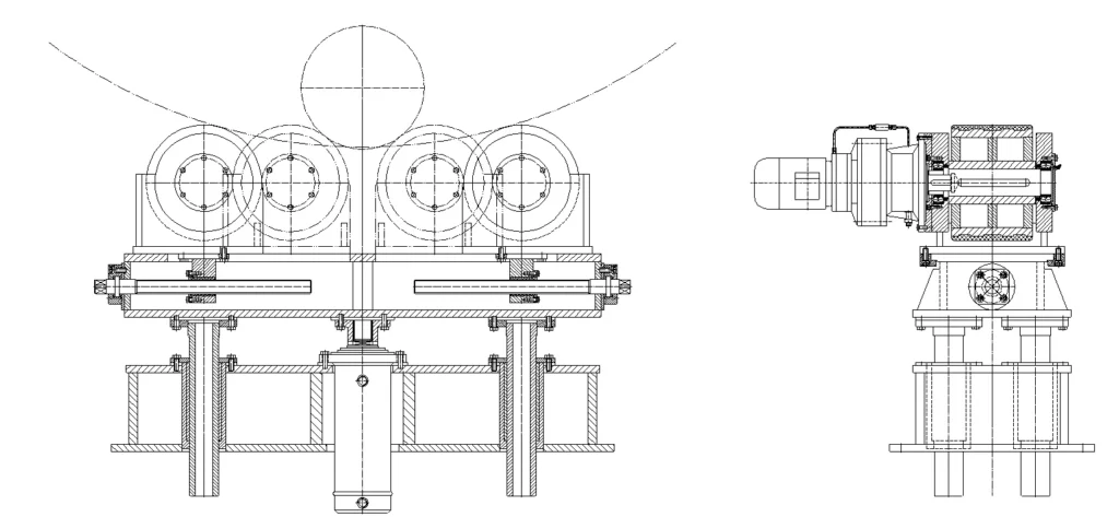
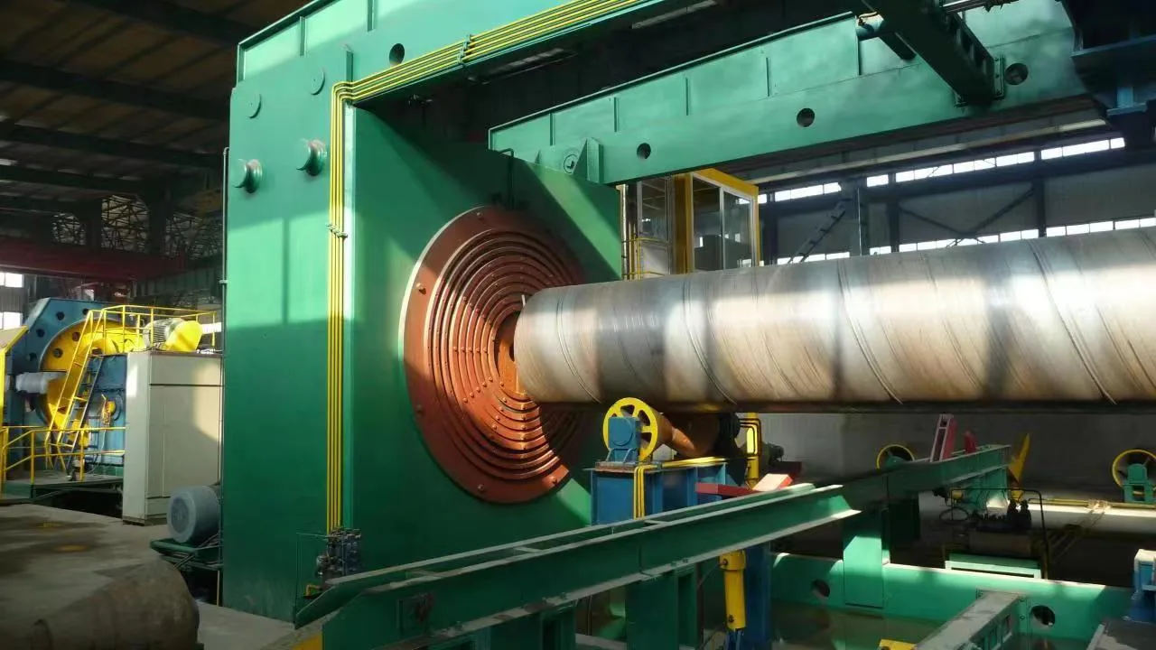
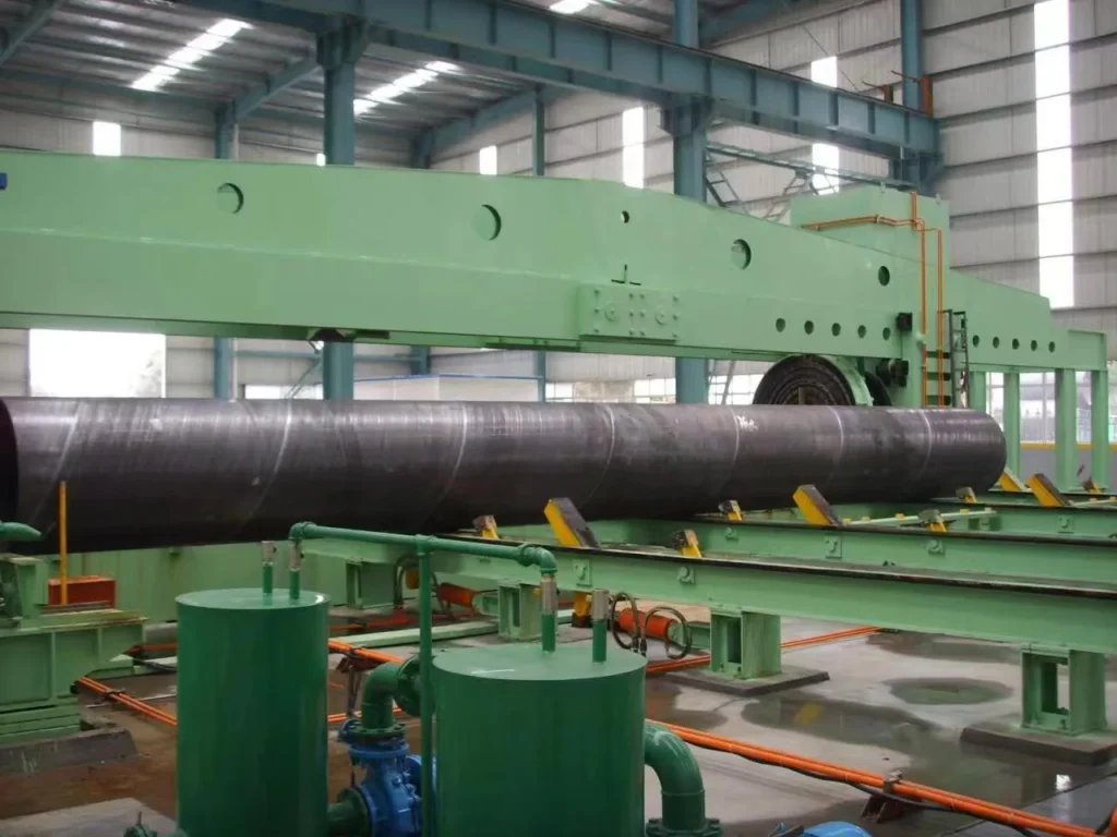
Spiral pipe mill with x ray and hydrostatic test
Two of the three stations are on both line grades, and the Φ820 grade has its own smaller equipment: a 160 X-ray unit and a 300-tonne hydrostatic tester. The Φ1620 grade carries the 225 kVA X-ray, the 1200-tonne tester and the offline ultrasonic station.
The reason for three stations rather than one is coverage, not redundancy. X-ray images internal defects in the spiral weld. The hydrostatic test proves the body and the weld under internal pressure.
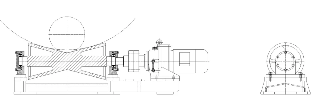
X-Ray: 225 kVA, Sensitivity 0.8–1.2%, Maximum Penetration 40 mm Fe
Inspection speed is set at 0.5 to 10 metres per minute, and the applicable pipe envelope is Φ219 to Φ1620 mm at lengths up to 12 metres.
The X-ray station’s electrical, geometric and performance figures are all specified. It runs at 225 kV and 8 mA, images the spiral weld onto a digital flat panel, reaches a maximum penetration of 40 mm of iron, and holds a static sensitivity of 0.8 to 1.2 per cent.
The station is specified against named imaging standards, and radiation protection requirements sit alongside them rather than being treated as an afterthought. The failure mode is equally direct: non-conforming exposure parameters or shielding produce both missed defects and a radiation safety problem.
The governing parameters are by name for the whole NDT group: tube voltage and tube current, inspection speed, probe frequency and coupling, and test-block calibration. What those decide is the defect detection rate and the compliance and traceability of the pipe that leaves the plant.
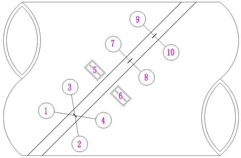
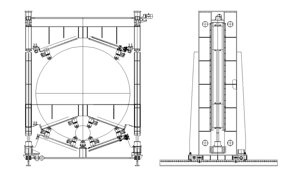
Hydrostatic Test: 1200 Tonnes, Computer-Monitored, Printed Record
The build includes a Φ800 main cylinder and a 31.5 MPa high-pressure pump, four tension beams in 16Mn at 600 by 80 mm with a safety factor of four, and Φ150 pin holes in 42CrMo. The hydrostatic tester has the most detailed mechanical specification of the three stations. It is rated at 1200 tonnes and tests internal pressure on the pipe body and the weld for strength and tightness.
Its working envelope is pipe Φ219 to Φ1620 mm at 8 to 12 metres.
The part a buyer’s quality department will care about is an equipment property rather than a promise: the station carries PLC and computer monitoring with printed output. The failure mode is a missing test or insufficient hold, and the consequence is a leaking pipe leaving the plant and a claim against it.
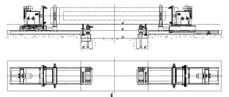
Off-Line Ultrasonic: Weld 100%, HAZ 25 mm Each Side, Body ≥35%, False Call ≤2%
Coverage is 100 per cent of the weld, 25 mm on each side of the weld into the heat-affected zone, and not less than 35 per cent of the parent pipe body. The ultrasonic station has a coverage specification and an acceptance specification, and the two should be read separately.
Acceptance is a false-call rate of not more than 2 per cent, zero missed calls on the sample pipe, and a pipe-end dead zone of not more than 300 mm.
The instrumentation is specified as well. The probe frequency range is 0.5 to 15 MHz, signal-to-noise ratio is not less than 28 dB and sensitivity margin not less than 52 dB, coupling is by the water-film method, and the channel count is 32 for the pipe body and 8 for the weld. Seam tracking uses a Japanese Kenshi laser image acquisition system.
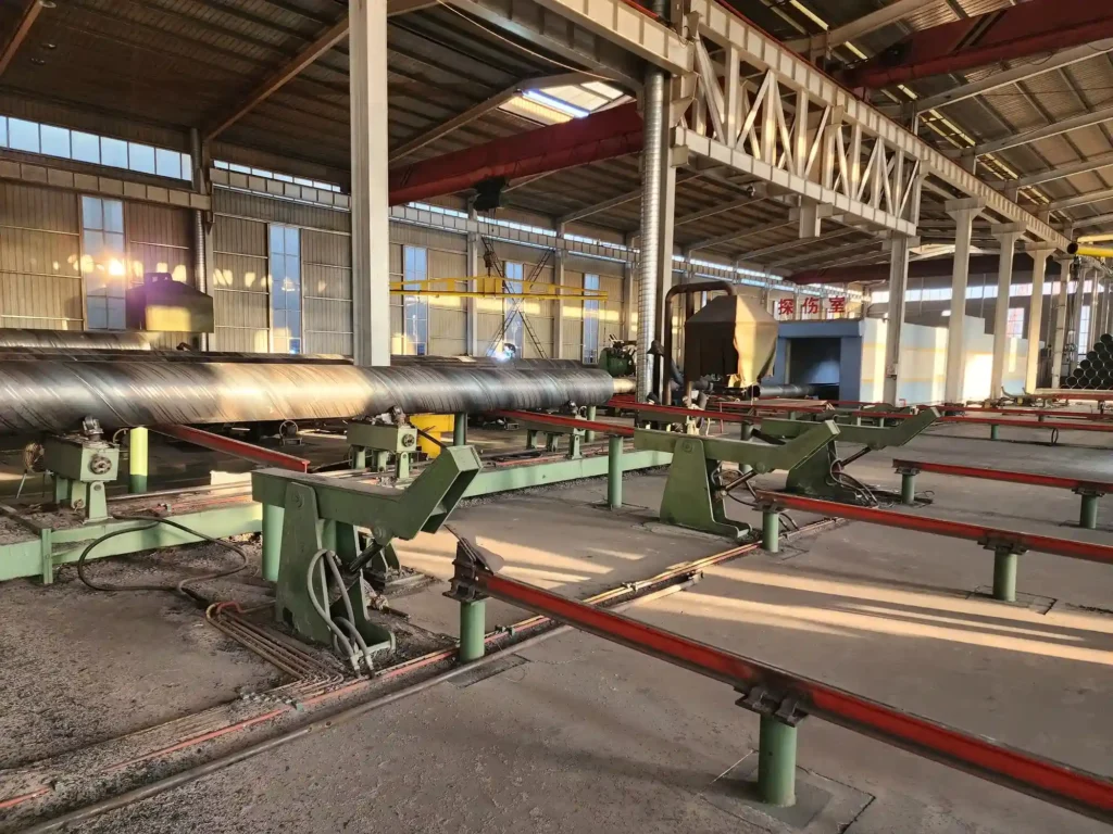
Spiral pipe mill with ultrasonic inspection
The failure mode for this station is calibration drift or unstable coupling, producing both missed and false calls and, importantly, a loss of traceability. That is why the coverage figures are paired with the false-call and missed-call indices — coverage alone does not establish that the station is reading correctly.
Responsibility is split along one clear boundary. On the equipment side, the three stations are supplied complete with quantified indices and printed test records. On the operator side, daily calibration, test-block re-checks and the disposition decision remain the buyer’s responsibility.
Who runs this chain, and what they are measured on
What that buyer is checking is diameter and wall coverage, whether X-ray, hydrostatic and ultrasonic are all present, and whether output matches the project milestone. The decision sits with the plant owner, the plant manager or the chief process engineer.
Oil and gas line pipe and water supply pipe place different demands on inspection.
For oil and gas transmission line pipe, Φ820 to Φ1620 mm pipe is produced to GB/T 9711 or API 5L and every pipe goes through X-ray, hydrostatic test and offline ultrasonic before delivery; the concern is that a straight-seam line cannot make the diameter at all and that the weld must clear all three stations first time.
For water supply and drainage pipe, the focus shifts to cost per tonne and output efficiency. Large-diameter thin-wall pipe loses roundness easily and is held in shape by external sizing.
Consumables and calibration continuity
Spiral submerged-arc welding is a consumable-intensive process, and the inspection chain inherits that. Welding wire, flux, plasma cutting tips and milling inserts are consumed continuously, with wire and flux consumption measured per tonne of steel, and a stable consumables supply is a key reason buyers return for a second line.
The line also ships with a flux drying, magnetic separation and recovery system, and two welding wire spools.
The buyer profile is specifically for the spiral line rather than borrowed from the company-wide list. It is a large-diameter spiral pipe maker working mainly on project orders, organising production in project batches, and as sensitive to standards and to the inspection chain.
Acceptance Criteria, Records Handover and Referenced Standards (Sources)
The Φ1620 grade additionally lists API 5L as an applicable standard, with X-ray and ultrasonic acceptance configured to API SPEC 5L, 46th edition. Two standards are the acceptance basis for the stations, and the scope of each is clearly defined. Both spiral line grades are built to GB/T 9711, and the X-ray and ultrasonic acceptance sections are specified to GB/T 9711-2017.
The finishing operation is requiring specialist non-destructive testing training or qualification, with each station judging pass, repair or reject against the standard, and with weld repairs requiring re-inspection.
What to ask the factory for
Three questions get a project team to a decision faster than a specification sheet does. Ask which line grade the quotation is for, because the Φ820 grade is without an offline ultrasonic station and the Φ1620 grade with one — that single difference changes which of the three stations exists on the floor.
Ask for the acceptance basis in writing per station, since X-ray and ultrasonic acceptance are tied to specific editions of the standards, and hydrostatic acceptance is tied to printed test records. And ask who holds the calibration duty after handover, because daily calibration and disposition sit with the operator, not with the equipment supplier.
Two scheduling facts belong in the same conversation and apply to this line specifically. Manufacturing lead time for a spiral line is set at 120 to 150 days, and acceptance is judged on continuous production of two sizes. Output on the Φ1620 grade is set at about 120 tonnes per 8-hour shift.
One planning fact is that a project team will need before the inspection stations are even ordered, because it decides the building. The Φ1620 line is shipped knocked down by unit, and its masses are about 138 tonnes for the main machine group and about 308 tonnes for the finishing group — the finishing group being where all three inspection stations sit.
The layout for that grade is a 36 by 24 metre main workshop within an overall 150 by 24 metre arrangement, with 32/16-tonne and 10-tonne cranes and a lifting height of not less than 6.5 metres.
Records handover is where the acceptance criteria become usable to the buyer, and it is set at station level. The hydrostatic station produces printed test records under computer monitoring. The ultrasonic station’s traceability depends on stable calibration and coupling.
Resource Downloads
From the Workshop
 SSAW or HFW
 What the Large-Diameter Tier Adds
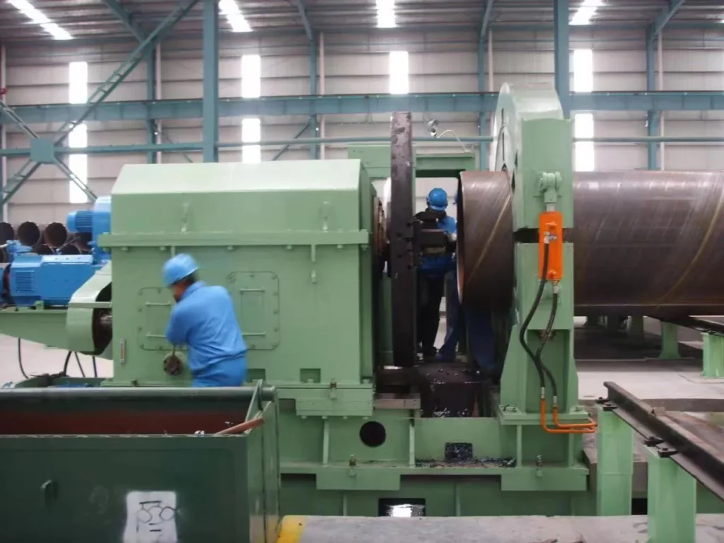 Changing Bore Without Changing Rolls
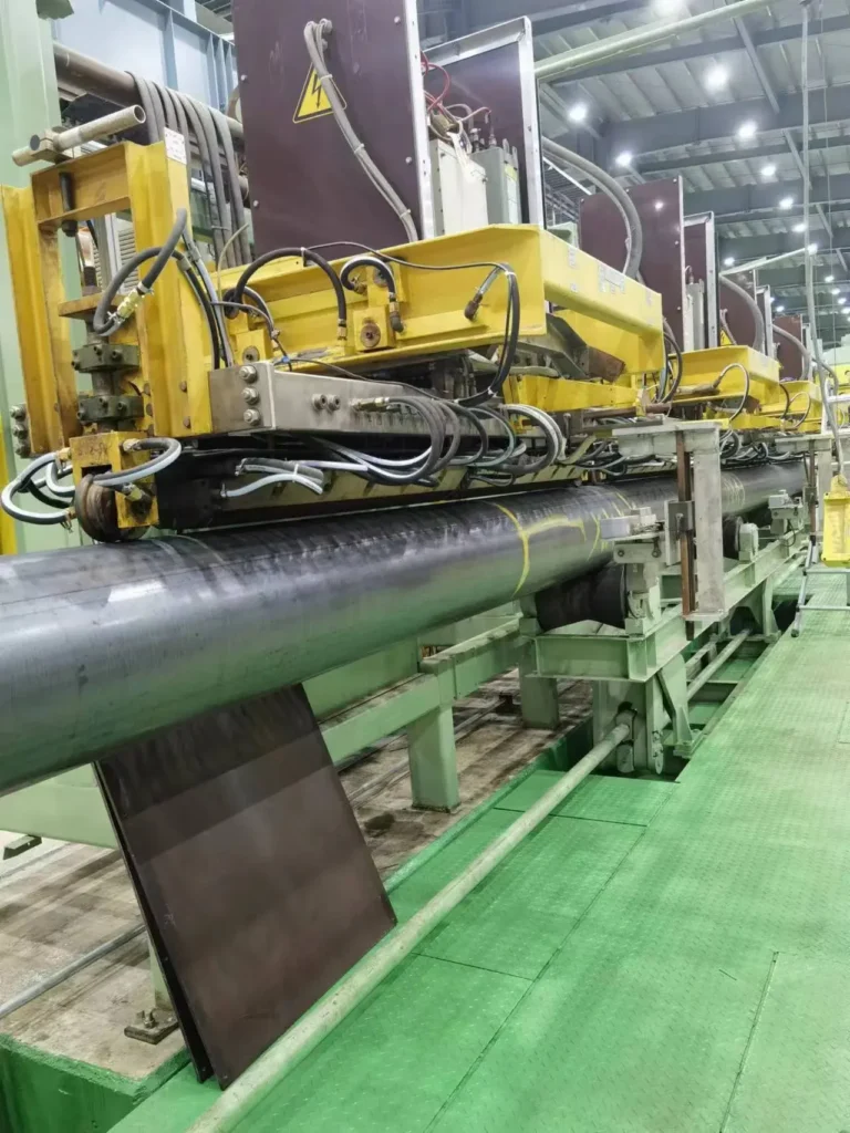 The API Pipe Mill Inspection Chain
Send Your Enquiry
Tell us the pipe outside-diameter range, the wall thickness and the output you need. An engineer reads every enquiry — it does not land in a general sales inbox.