
 Scan on WeChat
Home › Tube Mill › Large-Diameter Tube Mill › HG219
The seventh of the twelve model steps — Φ114 – Φ219 mm round pipe and 90×90 – 170×170 mm square section, on a 500 kW high-frequency welder.
Model Steps
In This Line
Quick Contact
Hebei TengtianYuanle@tentubemill.com
+86-311-83025332
WhatsApp +852 5425 3155
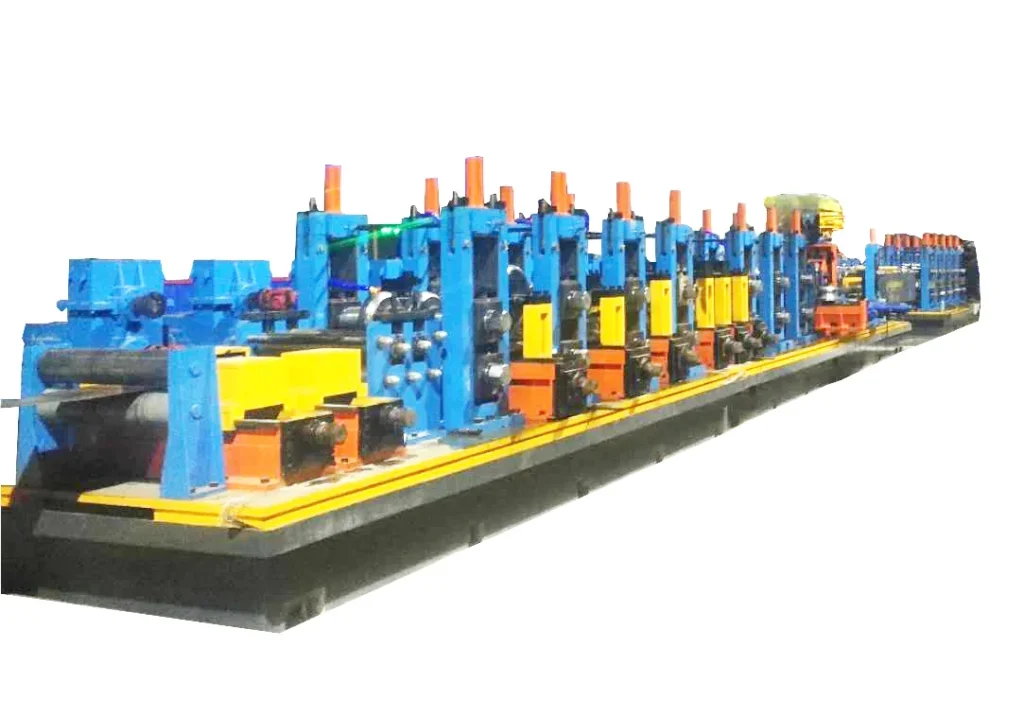
HG219 is the seventh of twelve HFW model steps. It makes round, square and rectangular pipe across Φ114–219 mm on a continuous high-frequency welded line: uncoil, level, strip-weld, accumulate, form, weld, size, flying-saw cut.
Line Specification — HG219×8.0
| Round tube outside diameter | Φ114 – Φ219 mm |
|---|---|
| Wall thickness | 4.0 – 8.0 mm |
| High-frequency welder | 500 kW |
| Square / rectangular tube | Square 90×90 – 170×170 mm; wall 4.0 – 7.5 mm |
Watch This Line Running
HG219 High-Frequency Welded Pipe Mill — O.D. 114-219 mm
Technical Specification Table
| Parameter | HG219 |
|---|---|
| Model step | HG219 — 7th of 12 (HG32 … HG630) |
| Pipe outside diameter | Φ114–219 mm |
| Section shapes | Round / square / rectangular |
| Welding process | High-frequency induction (skin & proximity effect) |
| Forming | Conventional roll forming (direct-square forming is a separate route) |
| Automation | Semi-automatic or full-auto PLC |
| Control | PLC industrial computer + variable-frequency drive |
| Material yield | ≥ 93% (line design; actual also depends on operation) |
| Welder power | 500 kW |
| Wall thickness (this step) | 4.0 – 8.0 mm |
| Manufacturing lead time (this step) | available on request |
Across the twelve steps welder power is matched to diameter and rises with it, over the range 150 kW to 1500 kW. The two endpoints: HG32 = 150 kW and HG630 = 1500 kW. The rating for HG219 is quoted per project.
Line Configuration and Scope of Supply
The HG219 line carries the same eight-stage configuration as the rest of the HFW range, and the units are what a buyer is actually paying for: 1. Coil car and expanding-mandrel uncoiler, pneumatically tensioned 2. Five-roller leveler — strip flatness before forming 3. Automatic shear-welder — joins coil to coil so the mill does not stop 4.
Spiral accumulator — strip buffer that makes continuous running possible 5. Forming and sizing mill — the core unit for shape, seam and dimension 6. HF induction welder — 150–1500 kW by step 7. Flying saw — cut to length at full line speed 8. PLC and variable-frequency control — keeps line speed and cut length repeatable
Continuous running is the point of the configuration rather than a feature of it. Without the shear-welder and the accumulator the mill stops at every coil change; with them, the joint passes through as part of an uninterrupted run — which is what the yield figure above depends on.
Post-weld cooling is part of the line and has to stay matched to welding speed; unstable cooling leaves poor seam structure and distortion.
What pipe in this diameter band is normally for. Two downstream uses dominate at Φ114–219 mm. The first is fluid transport — carbon steel welded pipe for oil and gas conveyance, municipal water and drainage, gas distribution, and chemical or heating lines. What that buyer measures is weld pass rate, diameter and wall coverage, non-stop coil change, and yield against energy use.
The second is structural and scaffolding tube — load-bearing building sections, scaffolding, and general mechanical structural parts in round, square and rectangular section. That buyer measures corner definition and straightness on square and rectangular sections, changeover speed between specifications, and electricity per tonne.
The distinction matters at purchase because it changes which part of the line is worth specifying up. A fluid-pipe plant is buying weld consistency and continuous running; a structural-tube plant is buying changeover speed and section quality. Both come off the same model step.
Where quality is won or lost on this line, in the order the strip meets it: incoming strip grade, thickness tolerance and flatness; forming roll material and heat treatment; HF power, frequency and welding speed; squeeze amount and seam alignment; sizing and straightening; impeder and induction coil condition; PLC and servo stability; operator setup at changeover; final inspection.
Nine control points, and only some of them belong to the equipment maker.
Automation level is selectable, semi-automatic through full-auto PLC, and it is a scope decision rather than a fixed attribute of the model step.
Size Change, Roll Wear and Running Cost
Material yield above 93% is what the line design supports — what is actually achieved also depends on the operation. On a conventional roll-forming line, changing size means changing rolls, and that is where a multi-size plant loses time. Two things reduce it: quick die change with servo positioning, and operator setup discipline — spec-change drift and commissioning scrap trace back to setup as much as to the machine.
- What wears, and what it costs to keep running:
- Forming and sizing rolls — replaced by output volume. These are machined at the works on its own CNC equipment, which is the direct answer to “can you still supply rolls in five years”.
- Induction coil and impeder — wear items replaced by welding hours; coil or impeder condition directly affects how the welding energy concentrates at the seam.
- Saw blades and cutting tools — consumed by cutting volume; a first batch normally travels with the line so the plant is not sourcing them during commissioning.
- Cooling water or emulsion, hydraulic oil and grease — specifications are supplied by Tengtian and the media are bought locally by the plant, which keeps a routine consumable off the import path and out of the lead time for a running line.
Responsibility boundary: the mill controls welding power, seam alignment and squeeze, sizing accuracy and straightening; the plant controls strip quality, operation and scheduling.
The same split applies to batch consistency after a specification change: servo positioning and quick die change reduce the drift, but the setup procedure at the changeover is the operator’s. Stating the split before the order is what keeps an acceptance meeting from turning into an argument about whose number 93% was.
Roll material and heat treatment govern how long the pipe shape holds; incoming strip grade, thickness tolerance and flatness govern how much of that is achievable at all.
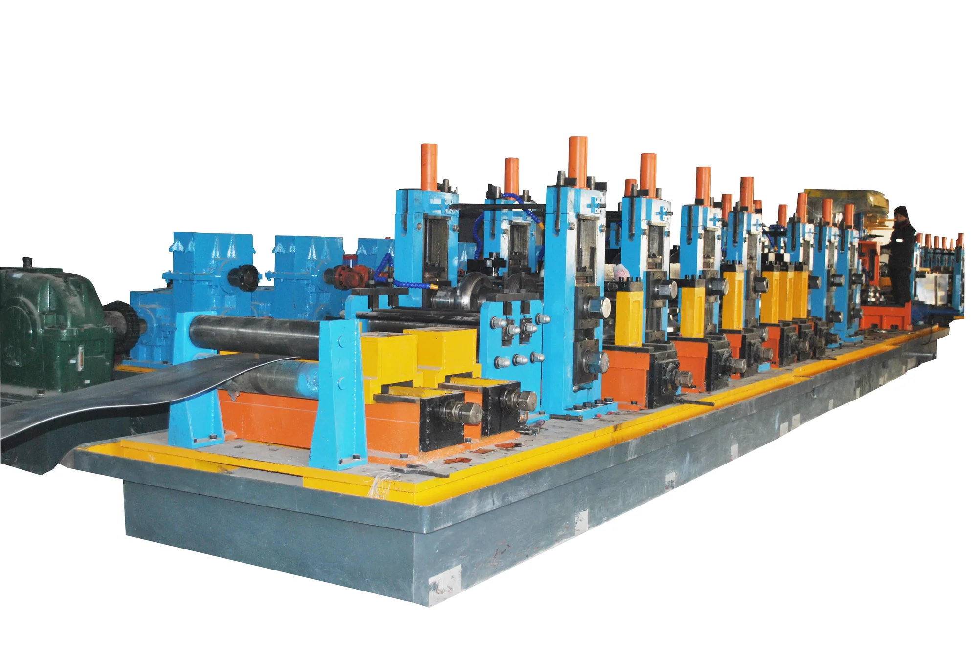
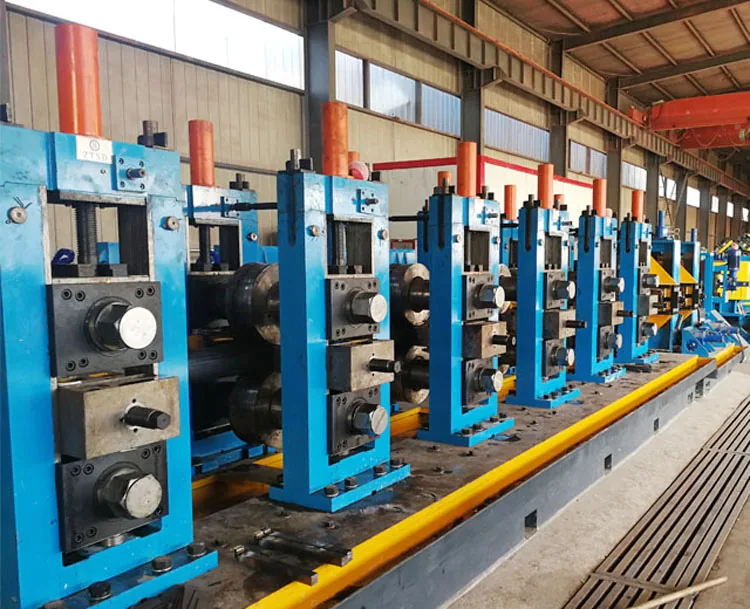
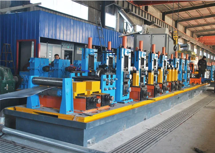
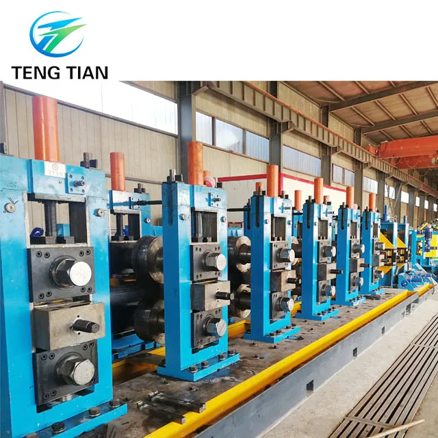
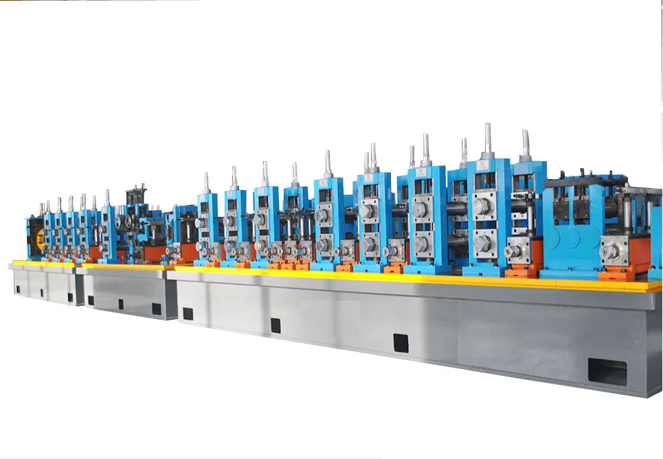
Tube mill for 219 mm pipe
Wear Parts and Consumables
Line Photos from the Works
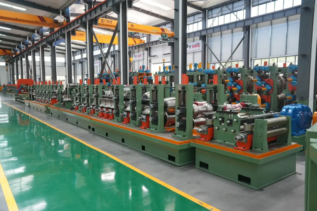
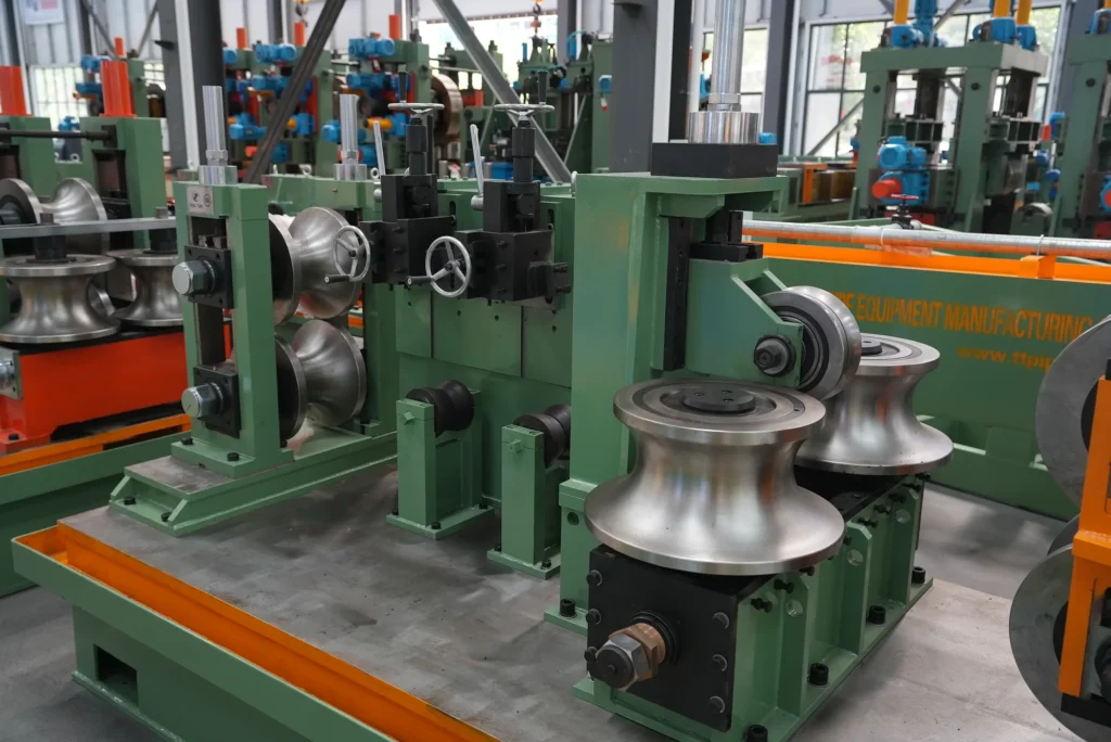
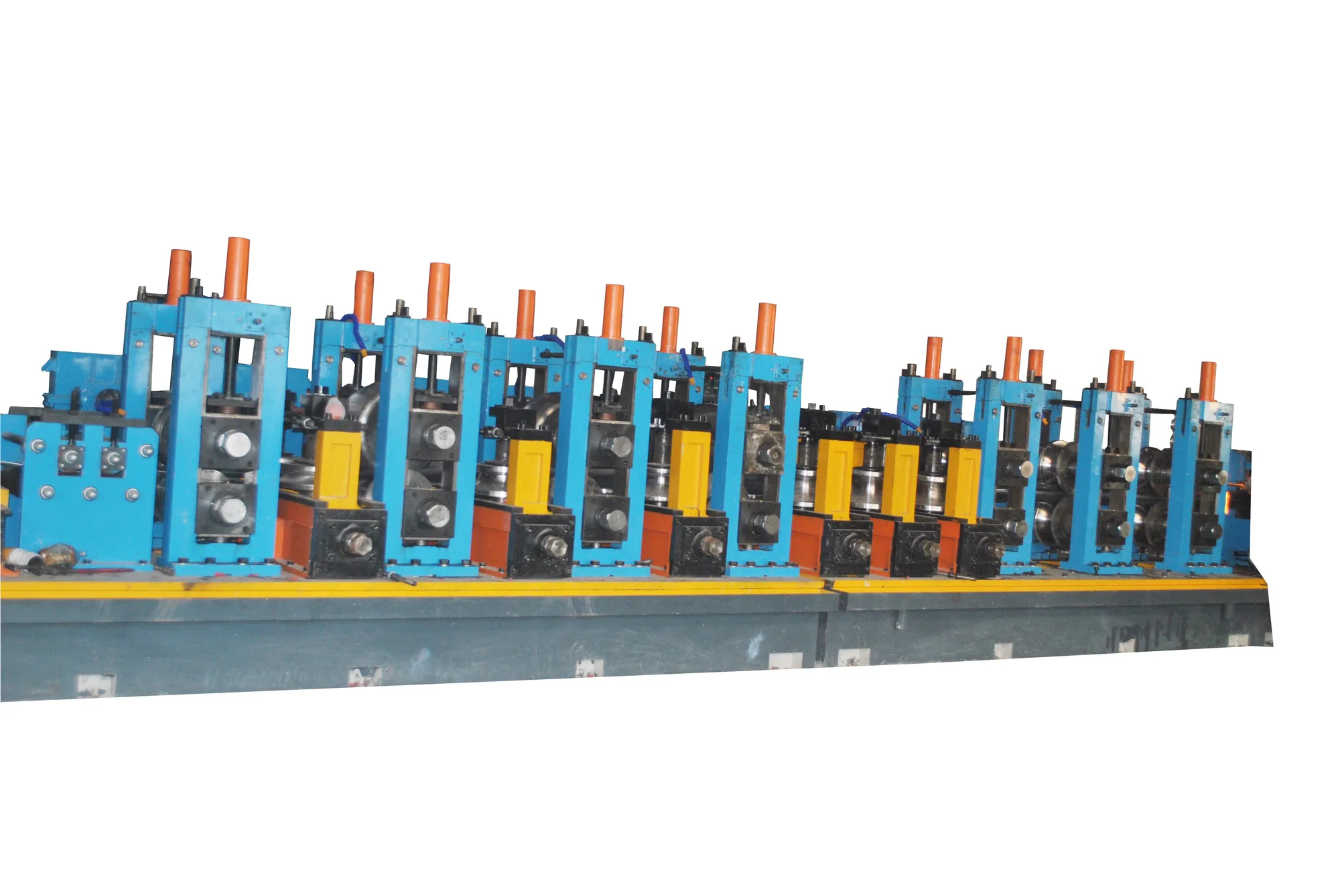
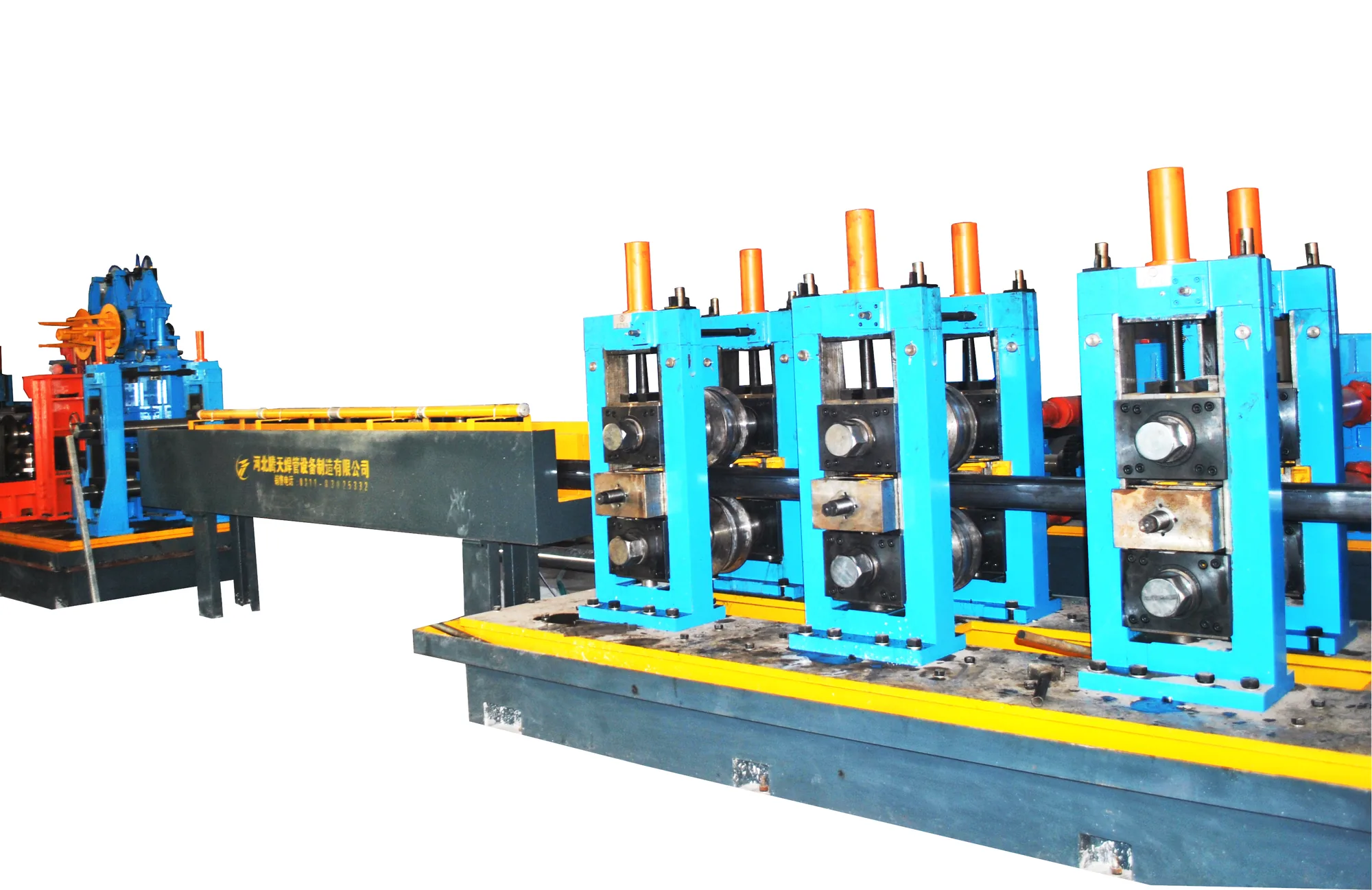
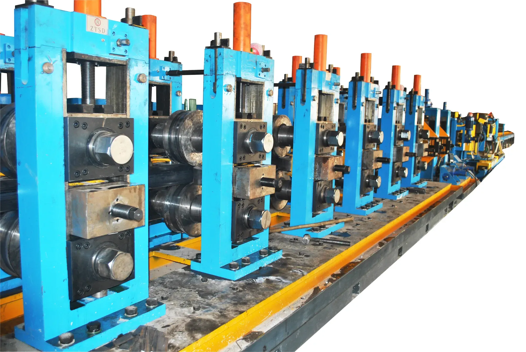
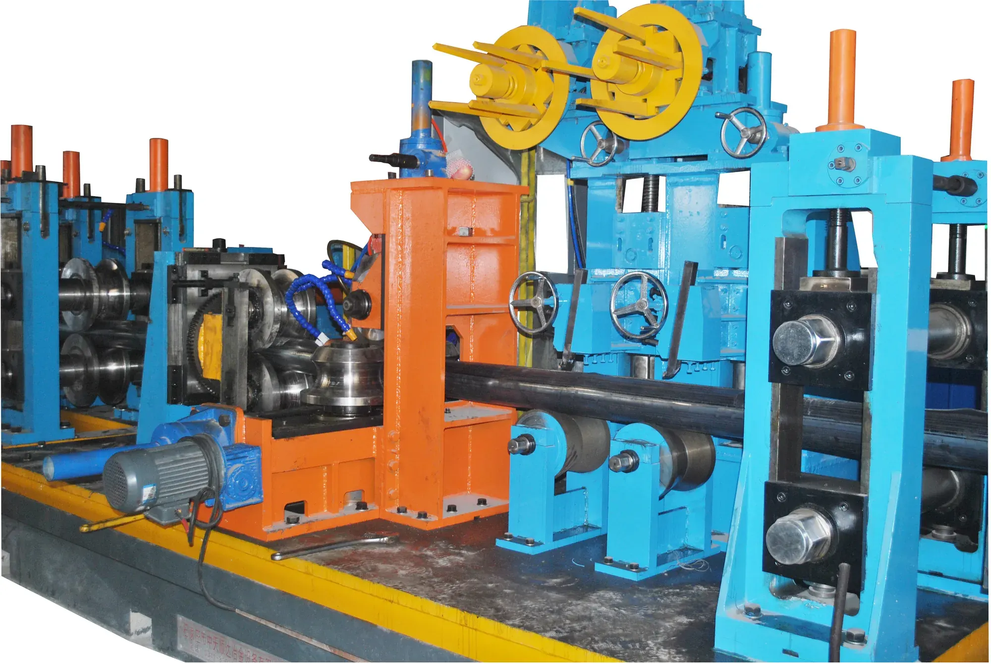
Eight photographs of this line, taken in our own workshop. Click any photo for the full-size image.
More from this line
 HG114
HG114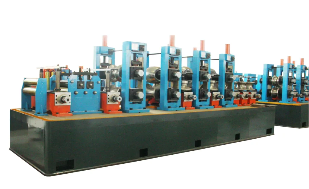 HG165
HG165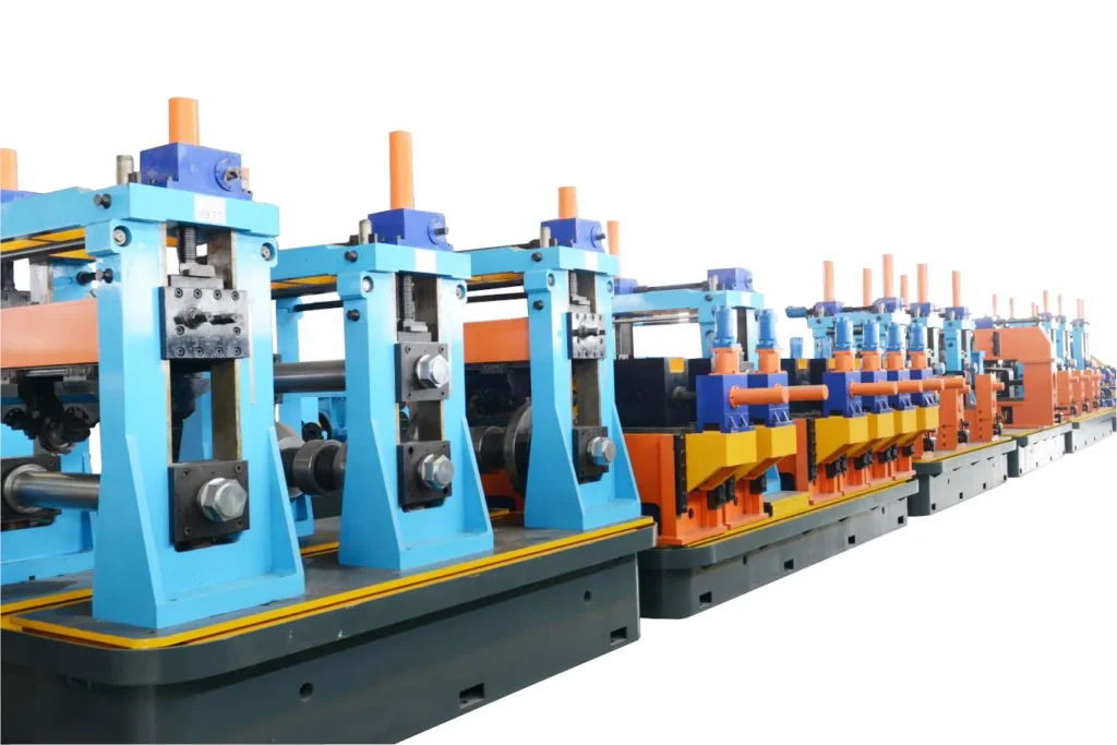 HG273
HG273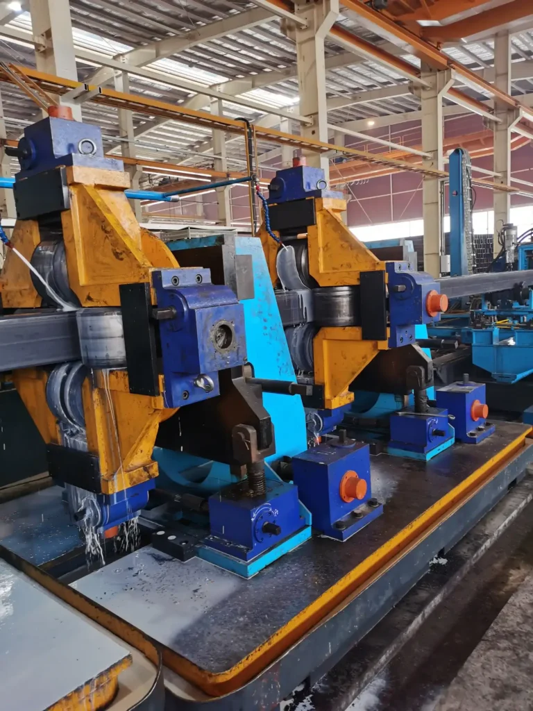 HG325
HG325Send Your Enquiry
Tell us the pipe outside-diameter range, the wall thickness and the output you need. An engineer reads every enquiry — it does not land in a general sales inbox.