
 Scan on WeChat
Home › Tube Mill › Small-Diameter Tube Mill › HG32
The first of the twelve model steps — Φ10 – Φ32 mm round pipe and 10×10 – 20×20 mm square section, on a 150 kW high-frequency welder.
Model Steps
In This Line
Quick Contact
Hebei TengtianYuanle@tentubemill.com
+86-311-83025332
WhatsApp +852 5425 3155

Every line in the HG series is one continuous mill: a coil goes in at the uncoiler and finished straight-seam pipe comes off the saw. HG32 is the first of the twelve model steps and, in this range, the one buyers reach for when the finished pipe is thin-walled furniture, fence or small fluid tube rather than structural section.
Line Specification — HG32×1.5
| Round tube outside diameter | Φ10 – Φ32 mm |
|---|---|
| Wall thickness | 0.5 – 1.5 mm |
| Square / rectangular tube | Square 10×10 – 20×20 mm; rectangular 20×40 mm; wall 0.4 – 1.5 mm |
| High-frequency welder | 150 kW |
Watch This Line Running
HG32 High-Frequency Welded Pipe Mill — O.D. 10-32 mm
Technical Specification Table
Wall thickness, line speed and shift output are confirmed against your pipe size, material grade and cut length at quotation. Send us those three and we will state the figures.
- Outside diameter range: Φ10 – Φ32 mm.
- Section shapes: round, square and rectangular. Most HG steps run all three.
- Forming: conventional roll forming; the direct-forming square option is a separate line type.
- Welding: high-frequency induction welding across the whole series.
- Automation: semi-automatic or full PLC control.
- Welder power: 150 kW.
The wall-thickness window for this step is 0.5 – 1.5 mm.
Line speed and shift output are available on request: a small-diameter mill’s speed depends on wall, grade and cut length.
Line Configuration and Scope of Supply
Replacement intervals in hours or tonnes are available on request. The unit list below is the series configuration, unit by unit, and applies to this step.
- Uncoiler with pneumatic four-link expanding mandrel, tensioning the coil as it feeds.
- Five-roller leveller, flattening the strip before it reaches the forming section.
- Automatic shear-welder, joining strip end to strip end so the mill keeps running between coils.
- Spiral accumulator, storing strip while the next coil is prepared.
- Forming and sizing mill — the core unit for shape, seam and dimension.
- HF induction welder, sized to the pipe range.
- Flying saw, cutting to length while pipe is delivered continuously.
- PLC and variable-frequency control tying speed, cadence and cut length together.
Tube mill for 32mm pipe
At the top of this step the mill is producing small pipe at high line frequency, so the two things that decide running cost are the saw and the impeder. Both are wear items we supply continuously: saw blades and cutting tools are consumed by cutting volume, and impeders and induction coils are consumed by welding hours.
Wear Parts and Consumables
Forming and sizing rolls are machined in-house on our own CNC equipment, which is the reason spare rolls stay available years after handover rather than becoming a sourcing problem.
Cooling water or emulsion and hydraulic oil and grease are process media: we give the specification, the buyer sources them locally.
Size Change, Roll Wear and Running Cost
Material yield is set at the line-design level: the process and automation support a yield above 93 per cent, while the yield actually achieved also depends on scheduling and operating practice on the buyer’s side. Changing size on a conventional roll-forming mill means changing the roll set. That is the baseline, and it is what this step does. The alternative — a combined mould with servo adjustment that changes size without changing rolls — belongs to the direct-forming square line, which is a different line type.
Weld fusion quality is on the equipment side — welder power matching, seam alignment and squeeze control — while strip quality and operation are the buyer’s.
Send the finished outside diameter, wall thickness and target output and we will size the step for you.
Where this step sits in the twelve
The series is a ladder, not a set of options: HG32, HG50, HG76, HG89, HG114, HG165, HG219, HG273, HG325, HG426, HG508 and HG630, each with its own diameter band. HG32 is the bottom rung.
Delivery, installation and what happens afterwards
The line is dismantled into units and shipped in containers: bare heavy frames braced and secured, precision and wear items in wooden cases with a spare-parts pack, and reassembly plus commissioning on site as part of the supply. Delivery takes 50 to 90 days.
Installation and commissioning are included rather than quoted separately, with on-site dispatch and round-the-clock online support behind them. There is a single point of contact, with a response time of under one hour.
Payment is staged — 30 per cent deposit and 70 per cent before shipment — with third-party escrow and multiple trade terms available.
Anonymised reference deliveries
Our lines are running in more than a dozen countries — mostly on construction tube, and also on fire-extinguisher tube, furniture tube and other sections.
What to send with an enquiry
Finished outside diameter, wall thickness and target output, plus whether the section is round, square or rectangular. Because welder power is matched to the pipe range, the step choice fixes it.
One more boundary on this step
Because this step is the bottom of the ladder, it is the one most often asked to reach below its band. It cannot: the twelve steps are the selection axis and this is the first of them. Correct line sizing is its own risk item — diameter against power against unit configuration — which is why a request below the band is answered with the band rather than with a promise.
What the line does control is drift after a size change: servo setup and repeatable positioning keep batch-to-batch dimensions consistent, and PLC plus variable-frequency control keeps line speed and cut length repeatable rather than operator-dependent.
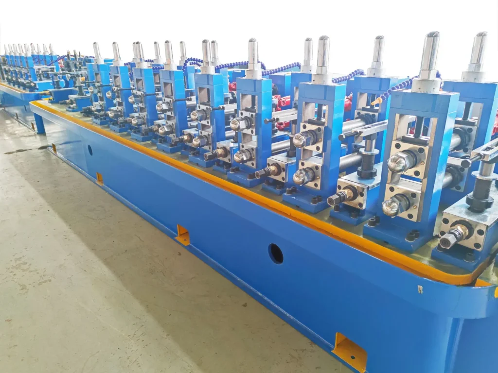
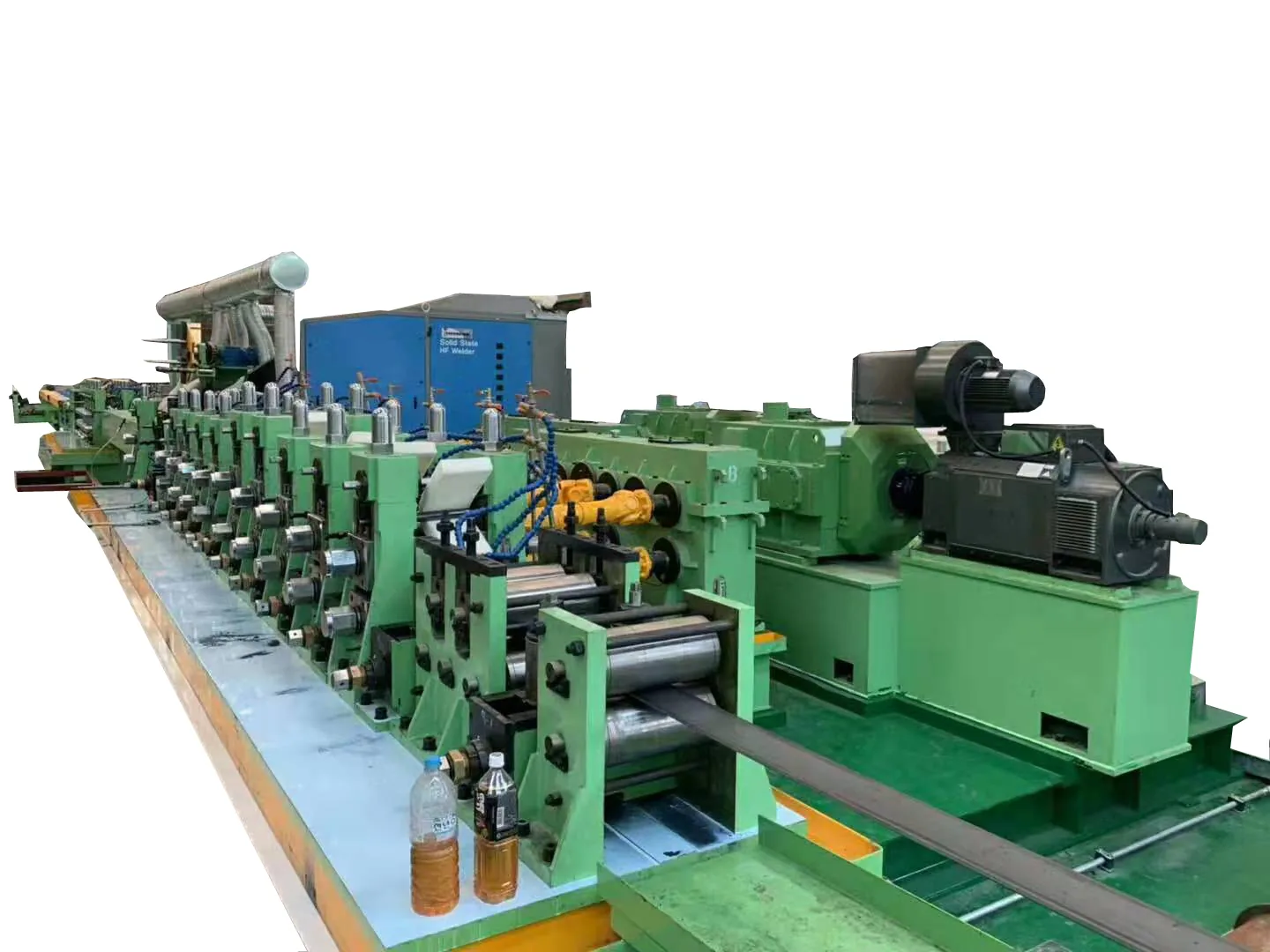
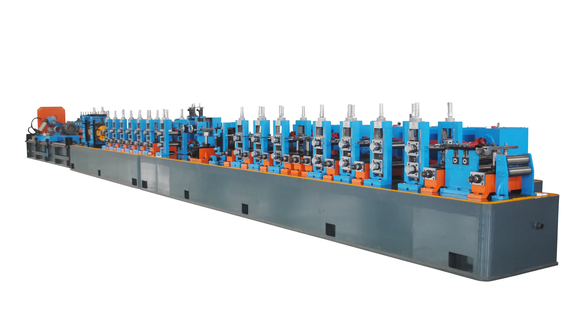
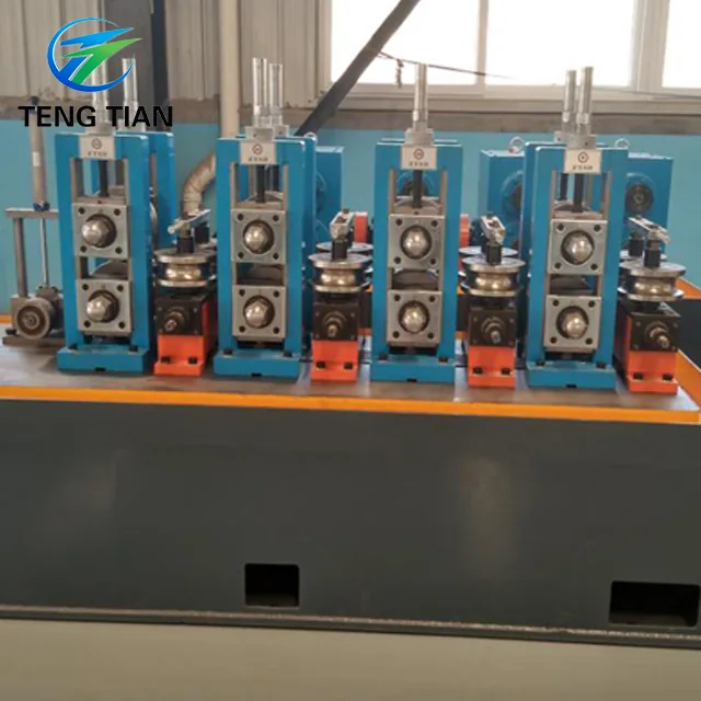
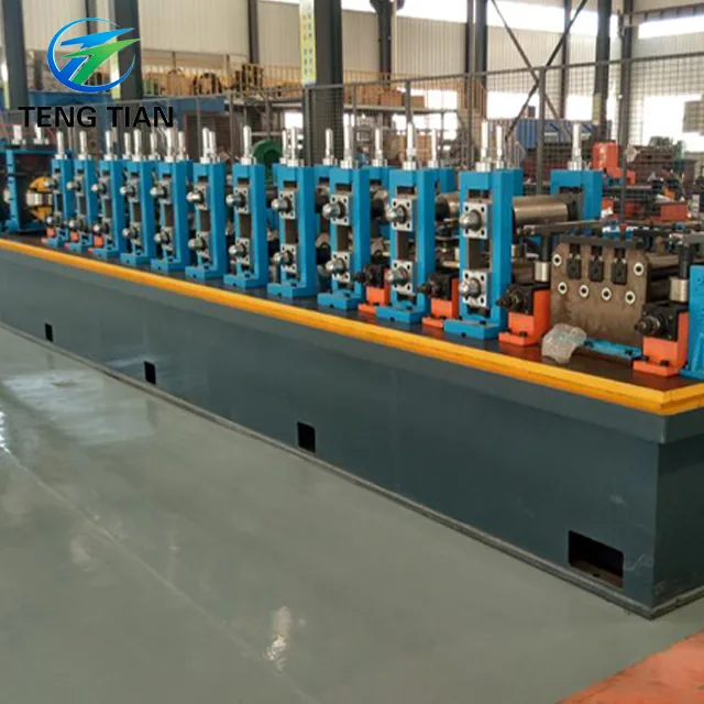
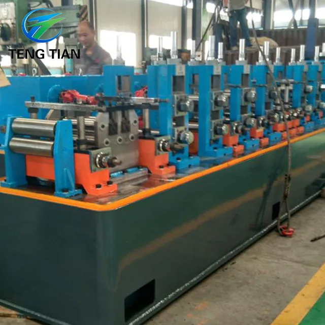
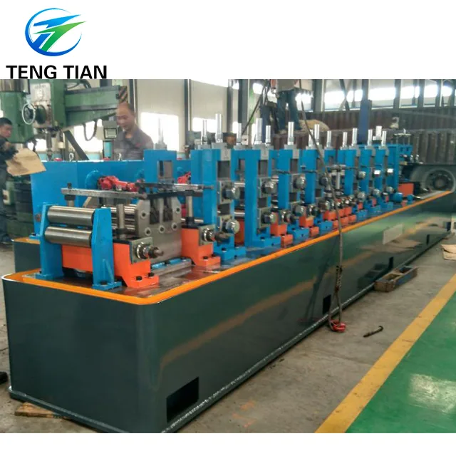
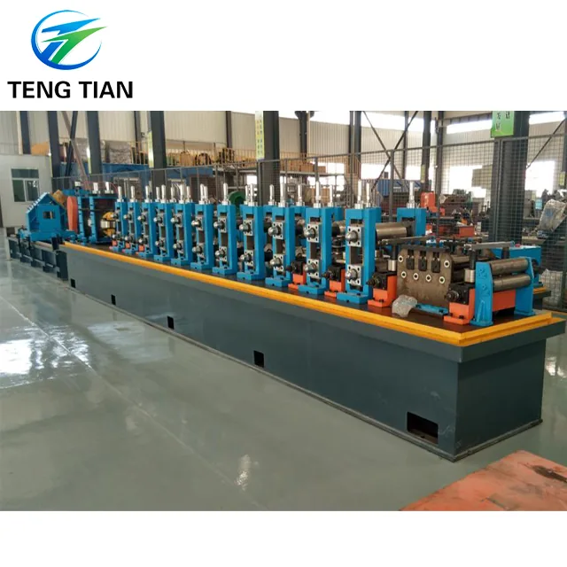
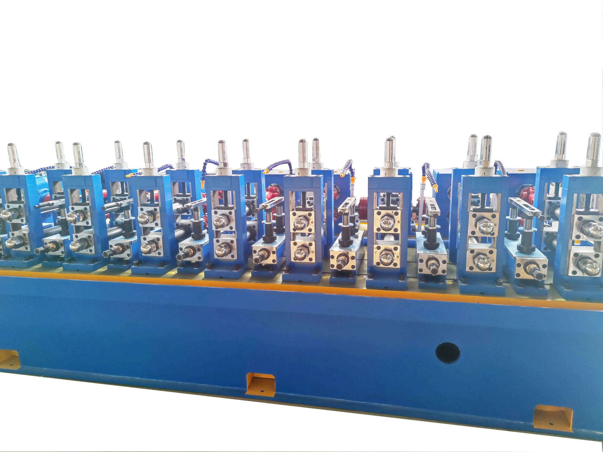
Line Photos from the Works
Eight photographs of this line, taken in our own workshop. Click any photo for the full-size image.
More from this line
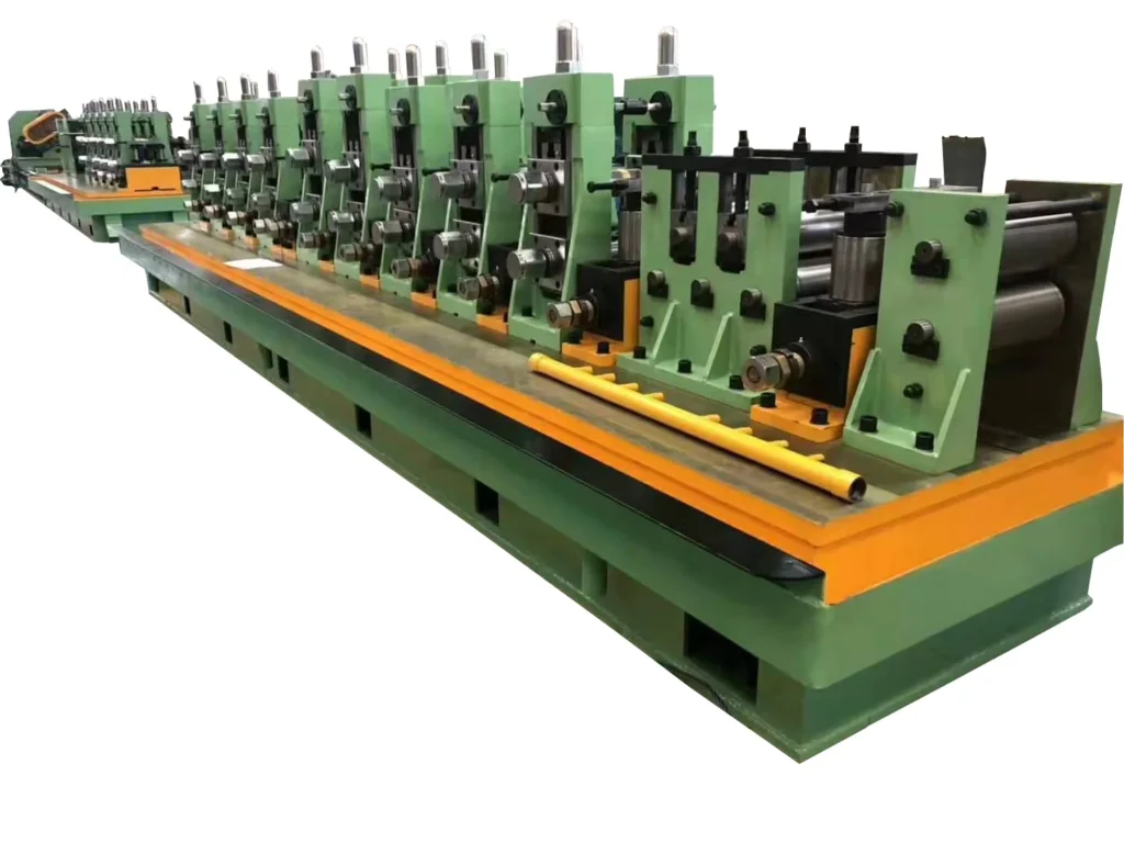 HG50
HG50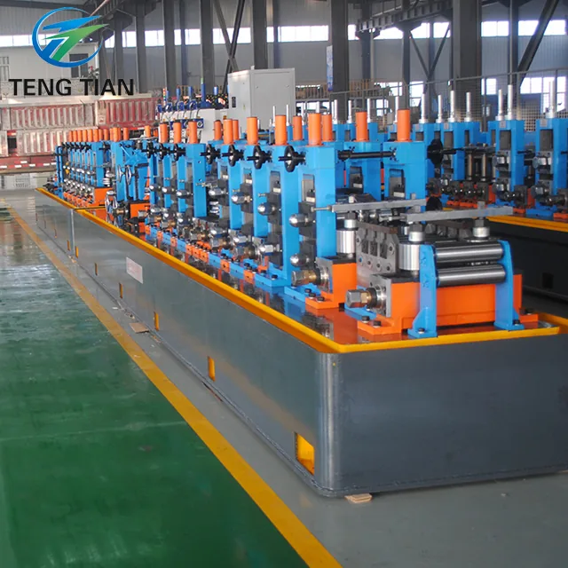 HG76
HG76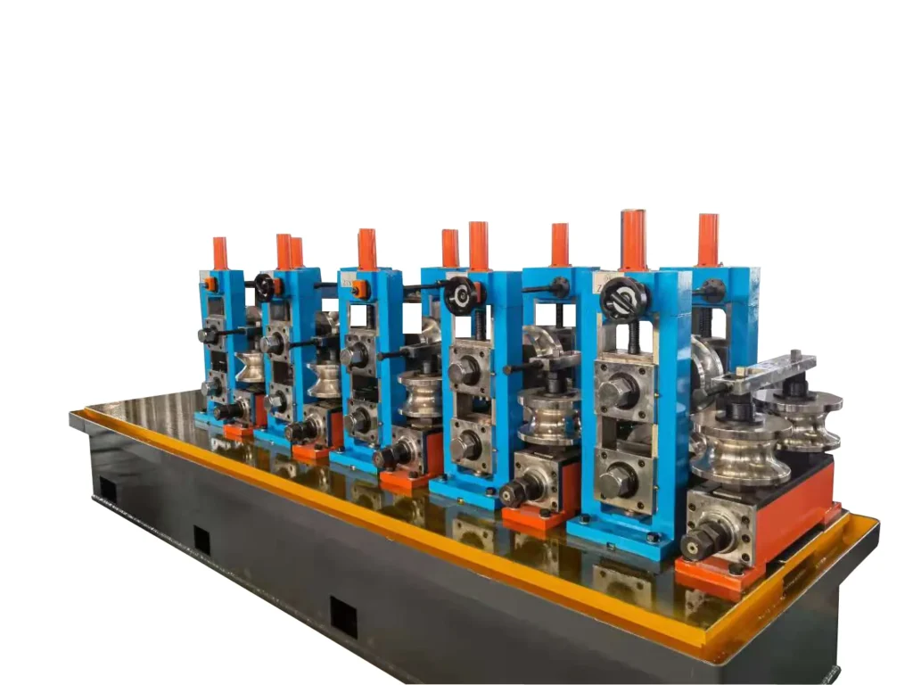 HG89
HG89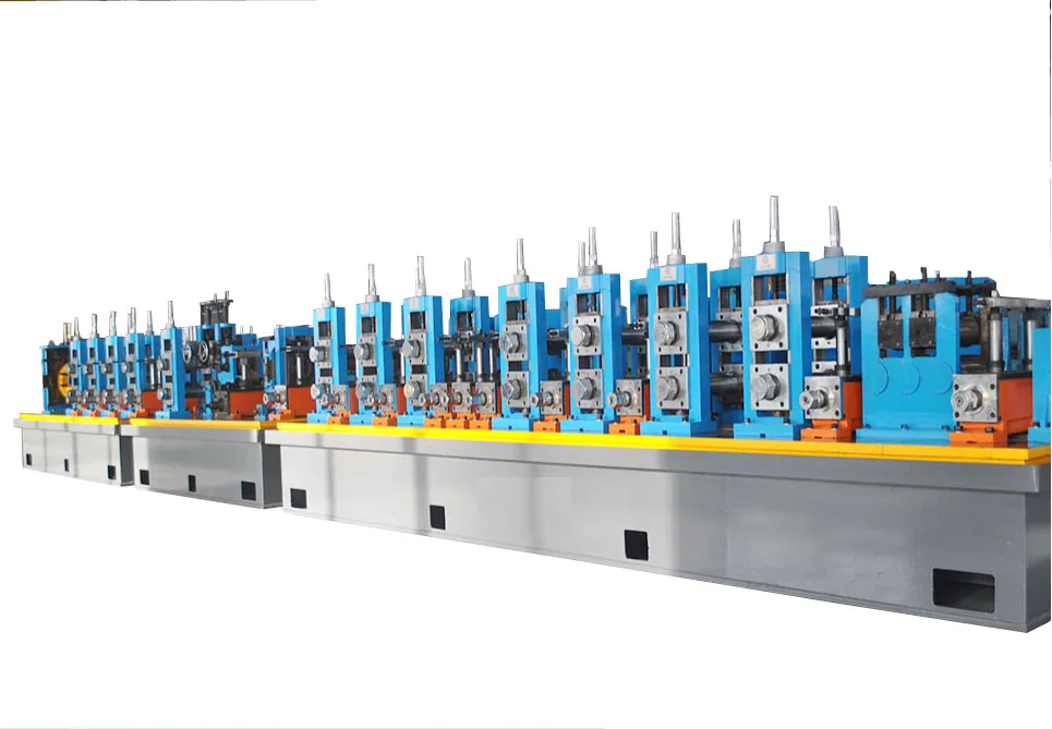 HG114
HG114Send Your Enquiry
Tell us the pipe outside-diameter range, the wall thickness and the output you need. An engineer reads every enquiry — it does not land in a general sales inbox.