
 Scan on WeChat
Home › Tube Mill › Large-Diameter Tube Mill › HG630
The twelfth of the twelve model steps — Φ325 – Φ630 mm round pipe and 250×250 – 500×500 mm square section, on a 1500 kW high-frequency welder.
Model Steps
In This Line
Quick Contact
Hebei TengtianYuanle@tentubemill.com
+86-311-83025332
WhatsApp +852 5425 3155
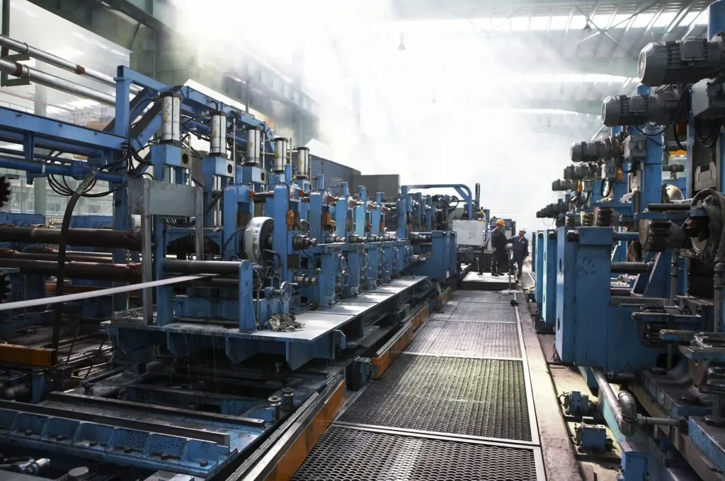
HG630 covers Φ325 to 630 mm and carries a 1500 kW high-frequency welder — the top of our longitudinal range. Above Φ630 mm, large-diameter pipe is produced on a spiral submerged-arc line instead.
Line Specification — HG630×16
| Round tube outside diameter | Φ325 – Φ630 mm |
|---|---|
| Wall thickness | 4.0 – 16.0 mm |
| High-frequency welder | 1500 kW |
| Square / rectangular tube | Square 250×250 – 500×500 mm; wall 4.0 – 16 mm |
Watch This Line Running
HG630 High-Frequency Welded Pipe Mill — O.D. 325-630 mm
Technical Specification Table
Model step: HG630 Outside diameter: Φ325–630 mm Welder power: 1500 kW Section shapes: round, square, rectangular Welding process: high-frequency induction welding, longitudinal seam Forming technology: conventional roll forming, or direct forming square Automation grade: semi-automatic, or full-automatic under PLC control Series wall range:
0.5–16 mm across HG32–HG630 Material yield: 93% or better by line design
Our high-frequency longitudinal line covers Φ10–630 mm, and HG630 is its last step. Above that diameter, a plant that needs line pipe, water and drainage pipe or structural pipe larger than Φ630 mm has to move to spiral submerged-arc welding. That is not a preference; it is the constraint that made the spiral line necessary in the first place.
The spiral mills cover Φ219–820 mm on the smaller build and Φ219–1620 mm on the larger, and one machine covers that whole band because diameter is changed by changing the forming angle rather than by building a line per size.
Between Φ325 and Φ630 mm both technologies are physically available, and the choice turns on production pattern rather than on size. Longitudinal high-frequency welding is continuous and fast, and suits volume.
Spiral submerged-arc welding is discontinuous with a welding speed of 0.5–3 m/min, covers a wide band on one machine, and can produce large-diameter heavy wall — which suits large diameter in medium batches.
Line Configuration and Scope of Supply
- Coil car and expanding-mandrel uncoiler, tensioning the coil.
- Five-roller leveller, flattening the strip before forming.
- Automatic shear-welder, joining coil to coil.
- Spiral accumulator, buffering strip so forming continues through the join.
- Forming and sizing mill, the core unit for shape, weld position and dimension.
- 1500 kW high-frequency induction welder.
- Flying saw, cutting to length at speed.
- PLC and variable-frequency control, holding speed and repeat cut length.
The process: rolls form the strip progressively into an open tube; high-frequency current concentrates at the open edges through skin and proximity effect and heats them to welding temperature; squeeze rolls press the edges together to form the seam under pressure; the tube is cooled, sized and straightened.
At this diameter the welder is the unit that most obviously scales, and the relationship runs in one direction: power is matched to the pipe range rather than the pipe range being derived from the power. More section to heat, and more metres per minute to heat it in, is what a 1500 kW rating answers.
Upstream coil preparation matters most at this end of the range. Our slitting and cut-to-length line handles strip 1–12 mm thick and 800–2000 mm wide in coils up to 32 t, holding slit width to ±0.2 mm, camber to 0.5 mm per 1000 mm, burr to 4% of material thickness and telescoping on the recoil to ±10 mm.
The line is the standard eight-unit high-frequency train, built at the top of the range.
Size Change, Roll Wear and Running Cost
The practical consequence is that a plant running the whole band will change size often, and which forming technology is quoted therefore matters: a conventional build changes size by changing rolls, while a direct-forming square build adjusts a combined die set by servo, with a roll saving above 90%. One exception: making 100 × 100 mm tube needs the upper roll on the final open stand changed.
Rolls are machined in-house on our own CNC equipment, so replacement rolls remain obtainable years after handover — a point that carries more weight at this diameter, where the roll sets are large and a bought-in replacement is not a quick order.
This step spans Φ325–630 mm, a range of 305 mm, and it is the widest span of any single step in the series — HG508 spans 289 mm and HG426 spans 261 mm. No performance or capacity conclusion is drawn from it.
Servo setup and direct forming also reduce drift after a size change, which is what batch consistency across a wide band depends on. Wall thickness, line speed and shift output are confirmed against your pipe size, material grade and cut length at quotation. Send us those three and we will state the figures.
Consumables and wear parts follow the series list — saw blades and cutting tools; impeders and induction coils; cooling water, emulsion, hydraulic oil and grease; and forming and sizing rolls as replacement items.
Impeder and coil duty at 1500 kW differs from their duty on a small step, so wear on smaller steps is no guide to wear on this one.
Ten factors decide whether the line holds quality across a run: incoming strip grade, thickness tolerance and flatness; roll material and heat treatment; welding power, frequency and speed; squeeze and seam alignment; sizing and straightening; impeder and coil condition; control and servo stability; operator setup and changeover; final inspection; and post-weld cooling matched to welding speed.
Forming and sizing rolls determine shape accuracy, roundness and squareness, edge definition and dimensional consistency; roll material and heat treatment decide how long that holds. Where they are wrong, the symptoms are early wear, diameter drift, uneven corner lines and repeated re-machining at every size change.
Applications and Output Examples
At Φ325–630 mm the demand is dominated by fluid transport rather than by structural section, though both apply.
Fluid transport pipe — carbon-steel welded pipe for oil and gas transport, municipal water and drainage, gas distribution, and chemical and heating pipework, measured on weld pass rate, diameter and wall coverage, non-stop coil change, and energy and yield per tonne.
API line-pipe configuration — high-frequency mill plus medium-frequency annealing, straightening, end facing, hydrostatic testing, ultrasonic and eddy-current inspection — whose steps are API 219, 406, 426 and 508 across OD 114–508 mm.
HG630 is above the top of that line’s coverage, so an API 5L requirement at Φ630 mm is not answered by adding the API package to this step. And a buyer needing pipe above Φ630 mm is on the spiral line, as set out above.
Two purchase triggers apply here: entering a new product type, which needs a dedicated line rather than an adaptation; and a large downstream order pushing a plant to add capacity fast enough to deliver on schedule. Two switching triggers apply as well, and one of them is specific to this end of the range.
Poor after-sales and spare-part supply from an incumbent supplier is the general case. The specific case is a plant that has outgrown its existing line: the reason for moving to spiral welding is precisely that a longitudinal mill is bounded at the top by its diameter limit, and no amount of upgrading changes that boundary.
A plant approaching Φ630 mm on an existing line is therefore facing a technology decision rather than a capacity one, and it is better made before the order that forces it than after.
As on every line in the series, responsibility divides as follows: the mill controls welding power, seam alignment and squeeze; sizing and straightening set dimensional accuracy and straightness; line design supports material yield above 93%. Incoming strip grade, thickness tolerance and flatness, and operation, remain the buyer’s side.
Structural and scaffolding tube — square, rectangular and round sections for load-bearing steelwork and general machinery components, measured on corner definition and straightness, changeover efficiency and electricity per unit.
Delivery, Installation and Training
Lead time is 50–90 days.
Control cabinets, impeders and induction coils, forming rolls and cutting tools travel in moisture-protected wooden cases with a spare-parts pack; heavy large-diameter frames ship bare, braced on cradles with designated lifting points and rust protection —
the arrangement we use for heavy lines in this class shipped by sea, which need specialist lifting and rust protection rather than more packaging.
Five operating steps need different levels of training: coil loading and threading, and shear-welding a coil join in time with the accumulator, need operator training; setting a new size needs a trained change crew, and on a 305 mm span that crew will be used often;
setting welder power, welding speed and squeeze and then running the process needs process-level training; cutting and collecting is routine.
After handover, support is a first reply through a single named point of contact, all-hours online support, on-site dispatch when required, and direct spare-part shipment. Behind that sits in-house CNC roll machining, an engineering team of twenty averaging twenty years each, and an owned production base open to factory audit.
Certifications and standards: GB/T 19001-2016 / ISO 9001:2015 (quality management system, certificate No. 18524Q11269R2S); CE for welded pipe equipment, UDEM No. M.2022.206.C72171; enterprise standard Q/GYLTT01-2023 for HGF150 high-frequency welded pipe equipment, published on the national enterprise-standard platform.
For pipe made to API 5L, see our separate API line-pipe configuration.
Export packing is specified per item, and this is the diameter where the split matters most.
Large diameter tube mill for 630mm pipe
Tube mill for 630mm pipe
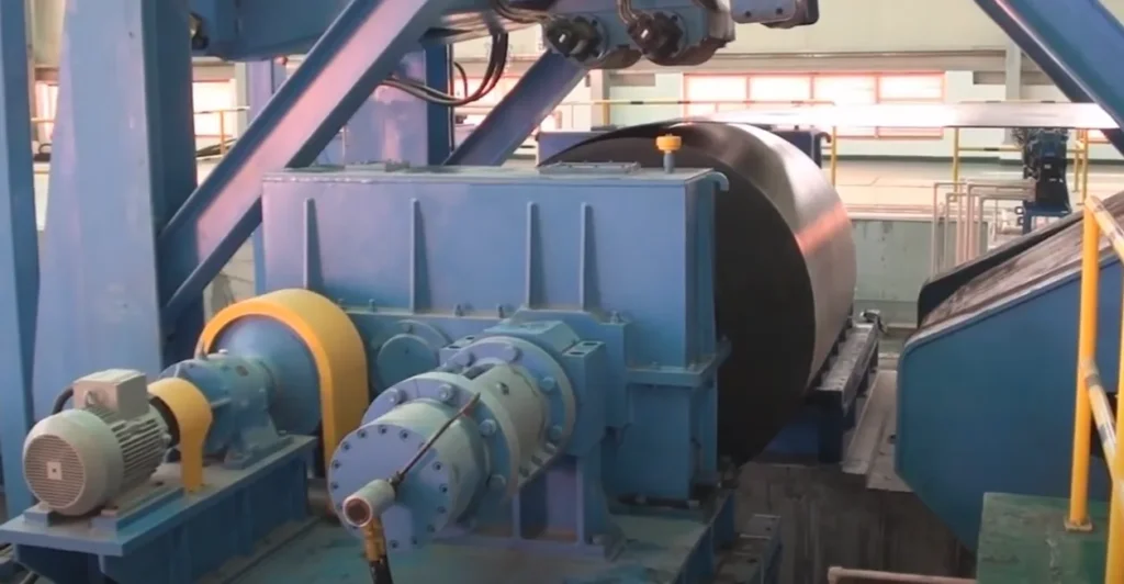
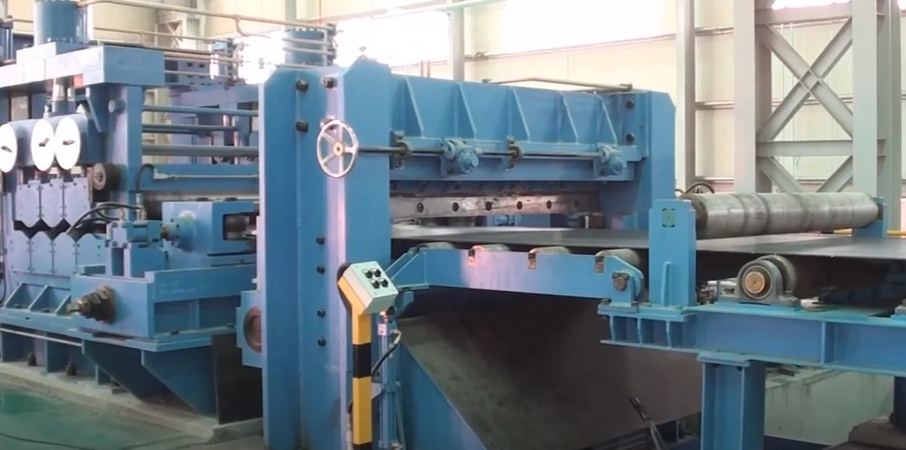
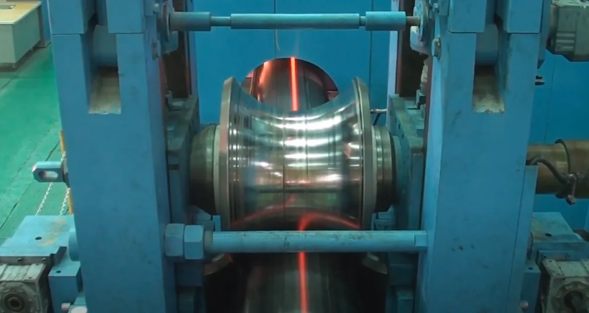
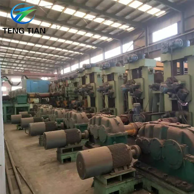
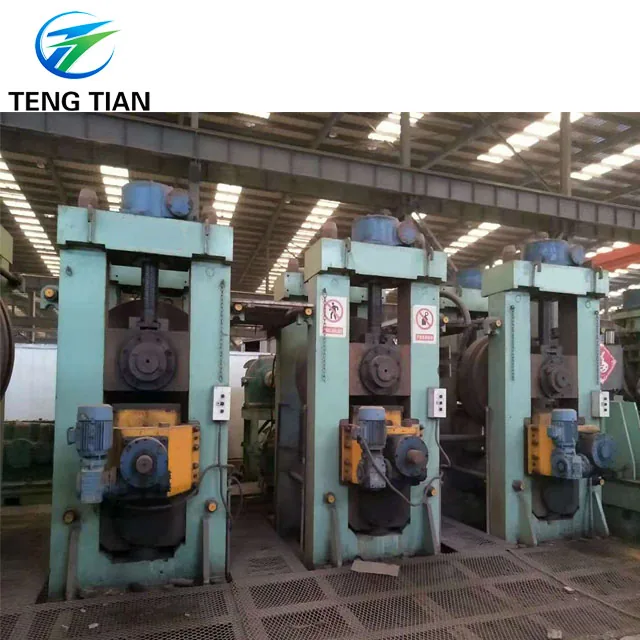
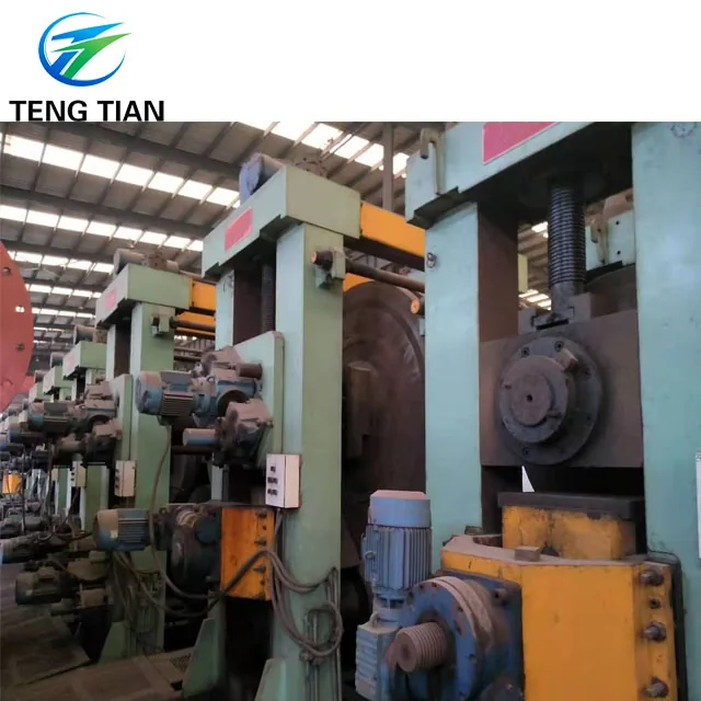
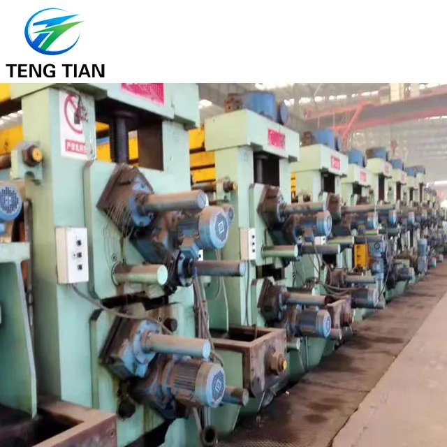
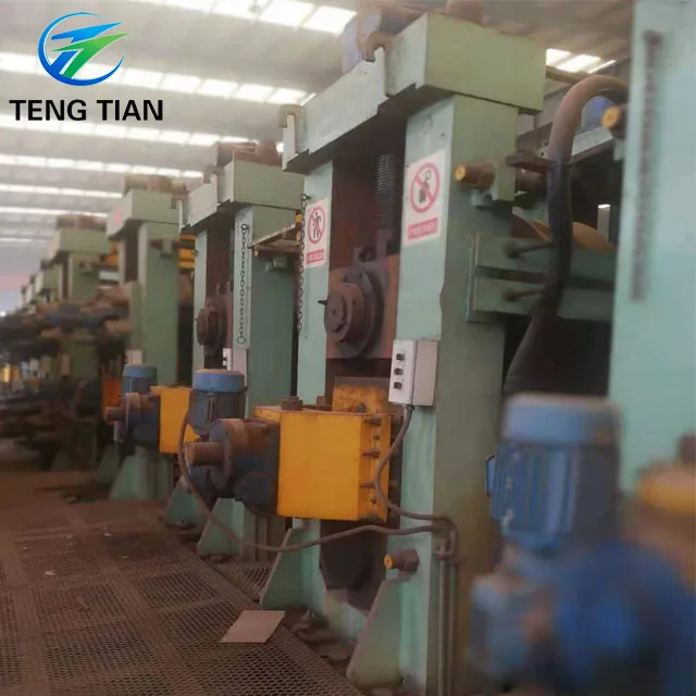
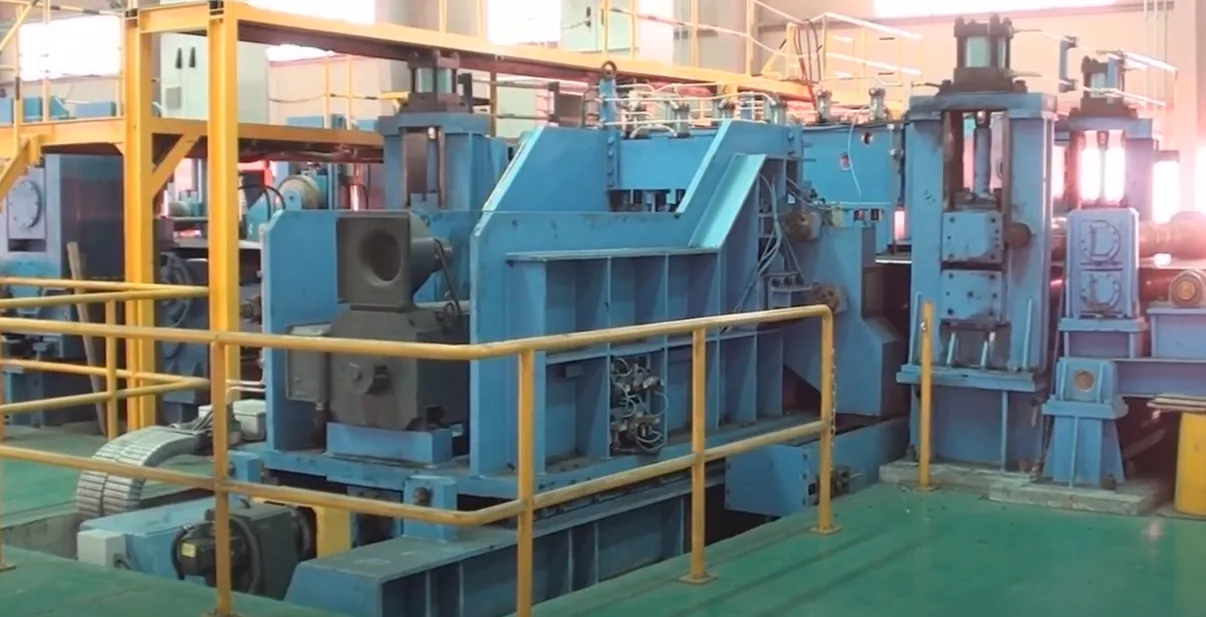
Line Photos from the Works
Eight photographs of this line, taken in our own workshop. Click any photo for the full-size image.
More from this line
 HG273
HG273 HG325
HG325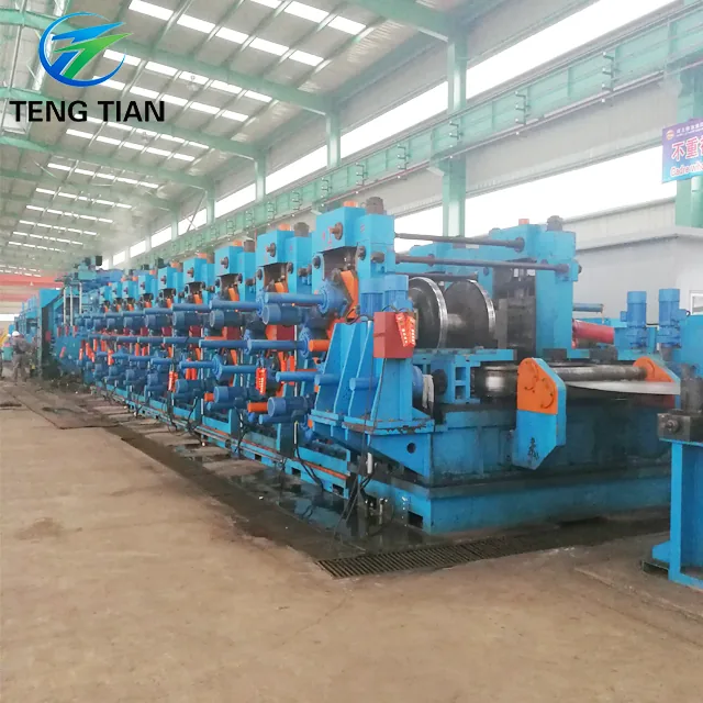 HG426
HG426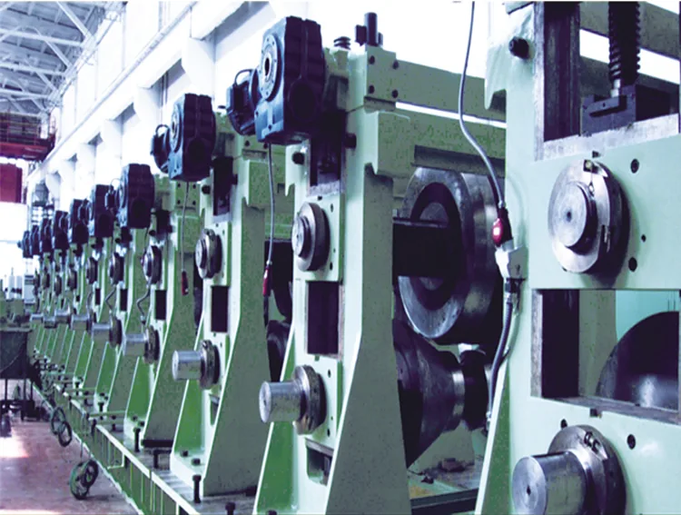 HG508
HG508Send Your Enquiry
Tell us the pipe outside-diameter range, the wall thickness and the output you need. An engineer reads every enquiry — it does not land in a general sales inbox.